Continue to Site

Welcome to our site!

Electro Tech is an online community (with over 170,000 members) who enjoy talking about and building electronic circuits, projects and gadgets. To participate you need to register. Registration is free. Click here to register now.

  • Welcome to our site! Electro Tech is an online community (with over 170,000 members) who enjoy talking about and building electronic circuits, projects and gadgets. To participate you need to register. Registration is free. Click here to register now.

Simple relay driver.

Status
Not open for further replies.

alphacat

New Member
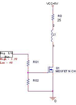
I'd like to driver the following 1W,5V relay.
I'm not using a protection diode in parallel with the relay's coil since the MOSFET **broken link removed** has already a built-in avalanche rated diode across connected from D to S.

VTn = 1.2V (min) to 2V (max).

I want the voltage drop on the MOSFET to be minimal, therefore i need RDS to be minimal.

Could you please help me figure out what should be the values of RG1,RG2 in order to get RDS minimal?

untitled-jpg.35409
 

Attachments

  • untitled.JPG
    untitled.JPG
    7.4 KB · Views: 2,428
Last edited:
What is the required coil current? For a simple relay driver at those voltages you're better off with a BJT rather than a MOSFET.
 
Last edited:
The required coil current is 200mA.
I'd rather using a MOSFET at this stage.
Regardless, i think that mosfets have lower RDS than the "RCE" of BJTs.
 
But you need a high gate voltage to realize that RDS on especially at higher currents.
According to the PDF at a current of 270ma, to get an RDS on of 250mohms you need a gate voltage of 10volts. From what I've been able to determien from the datasheet's graphs 3.3 volts is JUST barely enough to turn on the fet at your rated current at room temperature. So basically, you don't want ANY resistnace inline with the fet gate. If the I/O line is bidirectional RG2 isn't needed at all, and RG1 can be omitted as well depending on the I/O drive of the digital source. You really need a transistor boot stage for the fet gate or you will never see it's stated RDS on.
 
Last edited:
Yeah, the 3.3V drive to the gate is marginal even with a "logic level" FET. Can you just raise the Vdd on the ucontroller to 5V? A NPN transistor like a 2N3904 will work if you make the base resistor supply about Ic/20 to the base. Rb= (3.3-0.7)/(Ic/20)
 
Last edited:
... and don't forget to kick out "RD" (25Ω).

The voltage drop across a bipolar transistor is 0.7V. Supplying the relay with 5.3 instead of 5V won't do any damage to the relay - it will respond even faster.

Boncuk
 
I'm not using a protection diode in parallel with the relay's coil since the MOSFET **broken link removed** has already a built-in avalanche rated diode across connected from D to S.
You still need the protection diode in parallel with the relay. The intrinsic diode of the MOSFET is in the wrong place to clamp the back emf of the relay coil when it turns turns off.
 
Last edited:
Thanks guys.
Let me see if i got your point.

I need to get the MOSFET into its linear region, and the more i increase VGS, the more VDS will decrease? (= the more i decrease RDS).
So actually when I operate the MOS as a switch like here, i'd want it to be in the linear region with maximum VGS?

--
By the way,
RD = the coil resistance.

About the diode, thank you, you're right, i'll add one.
 
Last edited:
Hi,


As others have said, you still need a diode across the relay to clamp the
back emf when the coil is turned off.
I also have to agree that the NPN idea is better for your app because of the
very low drive voltage. Many bipolars can get down to 0.2v Vsat so there
shouldnt be any problem at all. Give it a try :)

MOSFET's are great devices, but that doesnt mean we have to use them
in every signal project we do.
 
Last edited:
Well, i'm doing it for studying purposes also, so i'd like to use the MOSFET and get the best out of it.

Could you please relate to my question about the linear region?
 
Hi alphacat,

trying to get the best possible results - including gaining experience - it is advisable to chose the best possible solution.

With a gate voltage of 3.3V (if at all if VCC=3.3V) you can't turn a MosFet fully on. RDS(ON) values in datasheets are normally based on 10V VGS.

In that particular case I'd select a BC337 (IC 650mA, requires 0.7V base voltage), strap it to the MCU output with a base resistor of 2.7KΩ to 4.7KΩ and have the relay click.

If math teaches you the way to go is wrong you already have had your "Aha-effect".

You can double it by using a MosFet and the relay won't click at all. :)

Ahaa! :D

Regards

Boncuk
 
Thank Bonuck.

I'm trying to understand simple thing please.
Do I need to:
1. get the MOSFET into its linear region?
2. Maximize VGS in order to minimize VDS and RDS?
3. Do the larger the VGS is, the smaller RDS is?
 
Thank Bonuck.

I'm trying to understand simple thing please.
Do I need to:
1. get the MOSFET into its linear region?

MosFets don't have a linear region. Take a look at the attached graph of a BS170

2. Maximize VGS in order to minimize VDS and RDS?
3. Do the larger the VGS is, the smaller RDS is?

2. and 3. contain the same question.

The higher VGS the lower is RDS(ON), hence ID increases. Again refer to the graph.

Boncuk
 

Attachments

  • RDS(ON).gif
    RDS(ON).gif
    22.1 KB · Views: 326
Last edited:
Hey Boncuk, and thank you for your help.

First, there is a region called linear/triode in MOSFET, and its where VDS < VGS - VTN.

The IDS current in the linear region is:
**broken link removed**

In my case, IDS ≈ 200mA.

Could i conclude from that formula that the more i decrease VGS, the more VDS will decrease, since the IDS current in the formula stays constant?
 
@alphacat, although your usage of the terms "saturated" and "linear/triode mode" of a MOSFET are technically accurate, the usage is not common outside of academia. Your audience here is mostly engineers who don't view a MOSFET through the formulas as you do. We develop a first-order understanding of behavior from V/I curves and discard the fine points as they are lost in manufacturing variances anyway.

For others who are first seeing this, hopefully this helps:

"Linear mode" in a MOSFET confuses most people. It's the region where the MOSFET exhibits Rdson. It's most similar to the state that we call "saturated" in a BJT.

To make matters worse, there's a "saturated" region in a MOSFET where the current varies with changes in gate voltage.
 
Not to poke fun, but alphacats posts are always from academia type perspectives. I think they're planning on developing cmos level devices at some point. Well on their way at least.
 
Well, i'm still a student after all :)
So much of what i learn come from the books

I didnt know that RDS on is related only to linear region, thanks.
 
What are the advantages using Mosfet over BJT? I mean, I play with 2N2222s and TIP-series all the time but I don't see many people playing with mosfets for their projects.
 
Are you talking about using MOSFET as a switch over BJT, or in general?

In general, MOSFETs have an infinite input resistance so they're useful in amplifiers, but the transconductance of BJTs is larger than of MOSFETs.
 
Last edited:
Status
Not open for further replies.

Latest threads

New Articles From Microcontroller Tips

Back
Top