Continue to Site

Welcome to our site!

Electro Tech is an online community (with over 170,000 members) who enjoy talking about and building electronic circuits, projects and gadgets. To participate you need to register. Registration is free. Click here to register now.

  • Welcome to our site! Electro Tech is an online community (with over 170,000 members) who enjoy talking about and building electronic circuits, projects and gadgets. To participate you need to register. Registration is free. Click here to register now.

Simple power mosfet control circuit wanted.

Status
Not open for further replies.

fenderman

Member
Hi All,
My background is Digital Electronics (MICROS,PIC.PLC's etc.) and I 'can do' simple electronics with NPN/PNP transistors and the like, but know absolutely nothing about MOSFETS, but was 'informed' that I should use a MOSFET for this requirement.
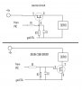
All I wish to do is use a MOSFET as a digital 'Switch' or 'Relay' to switch 5v at a maximum of 2A to a Servo Motor.
This Servo motor is being driven from a PIC chip, so once the control signal of 1 to 2ms pulse every 20ms has been established, a separate 'output' will be driven to 'Turn On' the power to the Servo.
The output pin of the PIC can source up to 25ma with (at worst case) VDD-0.7v, so around 4.3v, but it is nominal 4.7v.
The purpose of this is that when power is supplied to some servos without a stable control signal pulse, they act very erratically and ‘bounce’ around presumably hunting for a balance point, as both the PIC and the Servo are off the same supply, delaying the supply to the Servo seems to cure this.
Also, the PIC driver pin would be high impedance during PIC start up, and ‘MAY’ oscillate a little at high frequency until it is ‘initialised’ so thought that a but of Resistor/Capacitor mat be required on the MOSFET Gate. I was just thinking of a Resistor for the output pin to the gate, with a second resistor from the gate to ground in parallel with a small polarised capacitor.

Any help, suggestions, especially on which MOSFET part device to use would be greatly appreciated.

Thanks in anticipation.

Roy
 
I have used logic level mosfets as switches run directly from a PIC. Put a small resistor (e.g., 100 to 200 ohm) from the PIC to the mosfet gate to limit the current when charging it. That slows down the switching a little, but since it is effectively a one-time event, the effect on heating is negligible.

There are lots of such mosfets out there. As a starter, do you need/want to use a P-channel or N-channel? In the latter, the load is between the power and mosfet drain. The mosfet source is to ground. N-channel mosfets typically have lower RDS(on) than similar P-channel mosfets have. Another thing to look at is the gate capacitance/charge, as your charging current will be limited by the gate resistor. Finally, do you want something small (SMD) or will a TO-220 fit? With only 5V, you will not have a problem finding a device with an adequate Vds.

A large (TO-220), N-channel, logic-level mosfet to consider is the IRLZ44 or IRLZ24. As you obviously have discovered, there are lots of choices.

John
 
Hi John
Thanks for your quick reply, and info. If I have understood you correctly, I may be better using the drain circuit method.
I have attached a quick sketch of both the source and drain/sink with what I think is required.
I would very much apprecirate it if you could check them over and if possible if you have an idea of the R2 / C1 values, that would be great.
I only want to prevent the MOSFET from switching during PIC start up, hence the thought that a capacitor may just reject any spurious signals.
I was thinking of R2 being around 1K (with R1 being 100R).

I'm only vero building at the moment, so I think a TO220 style would be better, also, I don't think it would need a heat sink as the power is only higher during the short period that the servo motor is driving to its balance position. Thinking of trying the IRLZ24PBF from Farnell (Part # 1350883) ... and cheap enough at 49p.
Roy
 

Attachments

  • MOSFET DRIVER.JPG
    MOSFET DRIVER.JPG
    42.9 KB · Views: 2,526
Last edited:
Two things:
1) The "mosfets" in your schematics are connected backward. In the drain/sink model, that should be an N-channel and the Source goes to ground. See Fig. 10a for the IRLZ24 datasheet. That configuration is often called "low-side." In the other (P-channel model), the Source goes to V+, and it is called high-side.

2) I have never used the capacitor you show (C1). It will certainly slow gate turn on, but may not be needed. I have used the resistor to ensure the gate's state is known while the PIC turns on. As a rule of thumb, I have used a value of about 10X the gate resistor. It is certainly easy enough to determine if the capacitor is needed in you application.

John
 
Hi John,

I'll take a closer read at the data sheet, and try to get to grips with the fundamentals of Mosfets.

I'll get a couple of Mosfets inb the week and 'have a play' and see what works best ... I'll re=post my best findings at a later time.

Thanks again.

Roy

P.S. Just been looking around for data on the 'net and one of our suppliers here in UK (Rapid) is listing the STP36NF06L Logic Level Power Mosfet.
(**broken link removed**)
Datasheet indicates only one resistor ... I think this might be the one to use ... and only 28p ...
 
Last edited:
Datasheet indicates only one resistor ... I think this might be the one to use ... and only 28p ...

We are talking about two different resistors: 1) The resistor from the gate control switch (i.e., PIC in your case) to the gate; and 2) The resistor to ground (for N-type) or Vcc (for P-type) that is to ensure the mosfet is off at the start.

The first resistor is needed for two reasons: 1) to prevent oscillation of the gate when it is switched on rapidly (i.e., the gate is a capacitor and there is always resistance, so you have a potential RC oscillator); and 2) to limit current from the PIC pin. Gate resistors for the first reason are typically a few ohms to 20 ohms. The second reason is for the larger (e.g, 200 ohm) resistor.

The second resistor is to ensure a known starting state for the mosfet. In the circuit as you show it, it acts as a voltage divider. That is why I suggest a 10X ratio.

I am a firm advocate of experimentation. At the cost of these things, you can't lose much. I always buy at least three of each, like wine.

John
 
Last edited:
Ah, now I understand.

Like you say, at that price I can't loose, I'll take your advice and get a 'few'.

But maybe try to get them working, before the the wine !! :)

cheers for now, I'll re-post with results later.

Roy
 
I would normally make "R2" at least 100x to 1000x "R1", e.g. 2k2 (2.2k) to 22k. I would use lower values only when speed is an issue.
 
... and completely kick out the electrolytic caps connected to the gates.

You want to switch fast, not slowly I guess.
 
Thanks the info all,

I'll try it without the cap first.

Switching speed is not an issue, as the MOSFET is only 'holding off' the supply to the Servo motor until the PIC has fully initialised, then the output will be turned on, and will remain on until the power is removed again.

I was only thinking of the Cap to reject any spurious signals on the PIC pin that may be present due to it being high impedence during start-up, but as you say, it probably is not needed.

I'll try different values in the R2 leg to find the most suitable.

Thanks all again.

Roy
 
Status
Not open for further replies.

Latest threads

New Articles From Microcontroller Tips

Back
Top