Continue to Site

Welcome to our site!

Electro Tech is an online community (with over 170,000 members) who enjoy talking about and building electronic circuits, projects and gadgets. To participate you need to register. Registration is free. Click here to register now.

  • Welcome to our site! Electro Tech is an online community (with over 170,000 members) who enjoy talking about and building electronic circuits, projects and gadgets. To participate you need to register. Registration is free. Click here to register now.

simple phototransistor circuit

Status
Not open for further replies.

tony ennis

New Member
I pulled what I think is a phototransistor out of my junk bag.

It's a small clear flat rectangle with 3 leads.

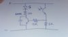
I hooked it up with +5v on one leg, and an LED -> 100 Ohm resistor -> gnd on the other. The LED came on when I applied the power. I covered the phototransistor completely and the LED didn't go out.

I didn't hook the middle lead up to anything.

The guy that gave me the bag o' parts thinks the phototransistor is a PN116PA or PNA1605F. I can't find a datasheet.

I'd like to make a circuit that if the phototransistor is cut off from light, the LED goes out. I think what I have would do that if I understood how the phototransistor worked, especially the middle lead. Any hints?
 
I think you have the photo-transistor connected like a forward-biased diode.
 
you'd have to use amplification, but it's not difficult.

one 2n3904 is enough. I've tested that on breadboard a while ago, and the LED responds to brightness.

you do not need A/D or OPAMP, not compulsory.
 
Heh, I am a total n00b, bear with me.

I measured 3.2v across the collector and emitter. So it seems that though the phototransistor prefers infrared, it does respond to all visible light.

I expected 1v across the LED leads assuming a 2.2 forward voltage. I am not seeing it. I tested the LED and it works.

Ok, I set the multimeter to 2000m DC. I assume that means 'use this setting for up to 2000 millivolts.' (It's my first multimeter, the instructions were useless.) If that's the case, then I think I am seeing 20mV across the LED.

Hmm. I covered the phototransistor up completely and the voltage didn't change a bit. More reading is necessary. But now it's time for bed.
 
Last edited:
Check the 'photocurrent' spec on the phototransistor, it probably mentions something in the microamp range. Unless you are using a photodarlington, it won't be able to switch enough current to light an LED, which requires ten milliamps or so to light.
 
You might need to shine upclose a very bright laser on the photo-transistor for it to conduct enough.
 
In fact, I did zap it with a laser. No difference. I think the LED needs to come out of the circuit until I get sane readings. My savvy friend recommends a much larger resistor than 100 Ohms, too. I didn't quite understand, but something about the phototransistor being a 'current based' device. So if the resistor is larger, then the voltage will go up too, as per Ohms law.

I have more reading to do.
 
The problem was that I misunderstood the diagram in the datasheet that showed which leads were the emitter and collector. The view is from the bottom, not the top as I had assumed.

I was able to coax 5v out of it (with a 5.x v input) by zapping it with a laser and putting a 14k resistor on it. Of course, I was unable to get an LED to do anything given the lack of current.
 
did you try to hook it up to a regular transistor?

often these transistors are 2-pole devices, maybe have internal connection.
 
Yeah, I connected the emitter from the phototransistor to the base of a typical transistor. I put the LED and resistor on the collector side of the transistor. I grounded the emitter. Then I hooked the LED counter thing I posted about a few days ago to this, on the collector side. Now when I shine the laser on the photodiode, the LED flashes and the counter increments.
 

Attachments

  • photoresistor.jpg
    photoresistor.jpg
    24.8 KB · Views: 3,494
Last edited:
Status
Not open for further replies.

Latest threads

New Articles From Microcontroller Tips

Back
Top