Continue to Site

Welcome to our site!

Electro Tech is an online community (with over 170,000 members) who enjoy talking about and building electronic circuits, projects and gadgets. To participate you need to register. Registration is free. Click here to register now.

  • Welcome to our site! Electro Tech is an online community (with over 170,000 members) who enjoy talking about and building electronic circuits, projects and gadgets. To participate you need to register. Registration is free. Click here to register now.

Simple linear power supply design

Status
Not open for further replies.
Hi tried to post a reply as in ronsimpson's post, but had some difficulty doing so. Here is my thoughts.
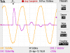
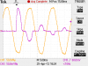
What I am sayings is if you want the power supply to supply a continuous 3A then the transformer needs to be rated at 3/.566. This figure came from two sources, 1 Triad Transformer Co. and 2 from a transformer manufacture friend of mine. As you know the peak voltage of the transformer is 1.414 times the rms. The filter capacitor will charge to near this value. Since the average load curreuld be 3A then the peak charge current is close the double that or 3/.566 so if the transformer is not rated at near 6A rms load current the winding supplying the current will heat up.
I am on a short vacation so I am away from home and don't have my notes with me so when I say the average value of a brute force filter capacitor is 3000uf per amp. I know there is a formula that has ripple voltage frequency and load current to calculate the exact value of capacitor required. I have built a great number of linear power supplies and have been real successful with the 3000uF/amp. I once built a high current linear power supply and the transformer was getting hot, so a did some research on max current.

Thanks you so much, really. You even replied when you are on a vacation. =)
 
Thanks you so much, really. You even replied when you are on a vacation. =)
Yes, I have a laptop computer I take with me. In the way of history, I have been in electronics about 60 years. I started out in about the 6th grade before transistors, circuit boards and a lot of other things. I made a living in repair, engineering and project management. I will have my 72nd birthday in about 6 months.
 
Do you think this type of heat sink can handle this? **broken link removed**

That heat sink looks like the ones available to me locally. Also, finding datasheets for heatsinks is a pain in the a**. Around 2celsius/watt would be ok right? So that would be around 60 celsius.

Actually, one of these power supplies should power 2 H-bridges. I'm current limiting those H-bridges to about 2A,peak. So I guess the average load would be around 3A.
 
Remind me of the minimum and maximum voltage drop accross the regulator. I reread all the threads and I had some difficulty determining those two voltages.
 
Remind me of the minimum and maximum voltage drop accross the regulator. I reread all the threads and I had some difficulty determining those two voltages.

Sorry, I was out for a while there.
Minimum and maximum voltage drop across the regulator? Are you talking about the absolute max rating of the regulator that I will be using? If so, I believe it is +40V (according to the datasheet).


Another question: If I want to include a fuse, Where should I put it? Do I put it on the primary winding? And given that the said maximum load of the linear supply is 6A, what should be the value of the fuse (its AC rated right?)?
 
Yes, I have a laptop computer I take with me. In the way of history, I have been in electronics about 60 years. I started out in about the 6th grade before transistors, circuit boards and a lot of other things. I made a living in repair, engineering and project management. I will have my 72nd birthday in about 6 months.

You are are a stalwart of everything good in Electronics and learning...

This world needs more people with your attitude. Kindly remind me/everyone here of your 72nd when it comes around ;)

Us youngsters can learn heaps from people like you....Eric you better show up too...not that you are old, just that you are wise as well :D

I am going to host an Internet party on Off Topic for the occasion. Can't wait. Please just remind me.

Kind regards,
tv tech
 
Last edited:
Yes, I have a laptop computer I take with me. In the way of history, I have been in electronics about 60 years. I started out in about the 6th grade before transistors, circuit boards and a lot of other things. I made a living in repair, engineering and project management. I will have my 72nd birthday in about 6 months.

Hey that's great. I hope you have many many more birthdays too, especially since you like electronics :)
 
If I were doing this, I'd ditch Q2and Q4, keep in R2 and R5 for current balancing, and put in a classical over-current limiting circuit using a resistor straight after the rectifier to short out R2 in the event of over-current, possibly with some hysteresis built in - that way you don't have to deal with current balancing to use the 317's own protection, and you know the transformer and rectifier are protected. I'd put a fuse in too. It's a more primitive circuit than what you have, but is tried, tested and robust.

Excuse my ignorance but what is D5 for?
Is R3 a dummy load? Only it seems rather small for a bleeder resistor.
 
Last edited:
If I were doing this, I'd ditch Q2and Q4, keep in R2 and R5 for current balancing, and put in a classical over-current limiting circuit using a resistor straight after the rectifier to short out R2 in the event of over-current, possibly with some hysteresis built in - that way you don't have to deal with current balancing to use the 317's own protection, and you know the transformer and rectifier are protected. I'd put a fuse in too. It's a more primitive circuit than what you have, but is tried, tested and robust.

Excuse my ignorance but what is D5 for?
Is R3 a dummy load? Only it seems rather small for a bleeder resistor.

I'm sorry, I'm confused about the thing about Q2 and Q4. I checked the circuit and you can't ditch both of them, you might have been confused of the adjacent names. Can you post a picture of what you are trying to say, please?

D5 is protection for the lm317 as recommended in the data sheet. This is placed since reverse current flowing into the lm317 when output is greater than the input voltage may destroy it.
And yes, R3 is a dummy load. It is small to simulate loads up to 6A(dc).


And oh, here's my report:
View attachment 63636
View attachment 63637

Yep, it's burnt. A failure. The diodes that exploded are D2 and D3.
The transformer I used is a 220 to 12-0-12V, 12A with the center tap ignored.
I tested it first, it was ok. Then I tested it with the power supply WITHOUT anything connected to the output. It didn't blow up.
Next, I connected a DVM (a portable one, battery powered) to the output to check the voltage. Then it went *POP* and *SPARKS* after I turned the switch on. I didn't expect it to blow since it has no load.
And As you can see in the picture, I only put in 2 3300uF filter capacitors instead of 6.

I went back to the simulator and found out this:
View attachment 63638

Damn. 160A surge? Woah. BTW, this simulation has 6A load, but the surge is also pretty high for low loads.
What should I do? Will a inductor help there? I'm guessing that this surge that killed the diodes is from charging the filter capacitors. I really don't know, I just want this to work. ;_;
 
You could implement a "soft start" circuit where the current is drawn through a resistor for the first second, or few milliseconds, whatever, then the resistor is shorted out for normal operation. It's easy to do using a relay, though a low Rds(on) mosfet would do the same job - I'm not too familiar with mosfets though.

Ok here's a diagram (based on your first one) to illustrate what I meant in the first place, with the soft start added in. The over-current protection will only limit the output to the 317's lowest voltage which is about 1.2volts? but that should be adequate for most things most of the time - any more severe conditions and the 317's own protection will cut in anyway. I'll leave it to you to calculate R91 and R92.

If you had 2 sets of contacts on the relay, the other set could ensure the output from the circuit is connected only when the surge current is finished. I'm thinking you could possibly build this into your over-current protection too - but you would need a latch/reset mechanism so it starts getting complicated again.
 
Last edited:
You could implement a "soft start" circuit where the current is drawn through a resistor for the first second, or few milliseconds, whatever, then the resistor is shorted out for normal operation. It's easy to do using a relay, though a low Rds(on) mosfet would do the same job - I'm not too familiar with mosfets though.

Ok here's a diagram (based on your first one) to illustrate what I meant in the first place, with the soft start added in. The over-current protection will only limit the output to the 317's lowest voltage which is about 1.2volts? but that should be adequate for most things most of the time - any more severe conditions and the 317's own protection will cut in anyway. I'll leave it to you to calculate R91 and R92.

If you had 2 sets of contacts on the relay, the other set could ensure the output from the circuit is connected only when the surge current is finished. I'm thinking you could possibly build this into your over-current protection too - but you would need a latch/reset mechanism so it starts getting complicated again.

Am I correct in thinking that the relay you are talking about is a mechanical relay that *clicks* whenever turned on? Is RLA the energizer coil of the relay? If that is so, wouldn't that short the rectifier? Also, isn't the rectifier 0V the same as ground (in the picture)? If I put R92 there, wouldn't it cause voltage fluctuations (which is what I'm trying to avoid in the first place).
Can you please tell me what is the purpose of the Q91 and R92? Sorry if I'm slow, I just can't seem to get it.

I also found a somewhat useful webpage: http://chemelec.com/Projects/Diodes-in-Parallel.htm
I think it's similar to what you are suggesting, albeit minus the relays.

You seem to reference the old circuit, I'll update the first post so that there wouldn't be mix ups. =)
EDIT: ugh... I can't edit the first post. I thought I could. -____ -,
 
Last edited:
Am I correct in thinking that the relay you are talking about is a mechanical relay that *clicks* whenever turned on? Is RLA the energizer coil of the relay?

Yes

If that is so, wouldn't that short the rectifier?

No, because the coil of the relay need only draw a few milliamps, or tens of milliamps

Also, isn't the rectifier 0V the same as ground (in the picture)?

Yes, sorry my bad - please excuse my very poor use of circuit symbols! It's all just the negative rail from your rectifier, aka ground, aka 0v since it's a single rail supply. In a dual rail supply it would be 0v or ground, but not the negative rail since that would be negative relative to ground. But of course you know that and it's not actually relevant here... Apologies for creating confusion!

If I put R92 there, wouldn't it cause voltage fluctuations (which is what I'm trying to avoid in the first place).
Can you please tell me what is the purpose of the Q91 and R92? Sorry if I'm slow, I just can't seem to get it.

I just realised I put in Q91 backwards! This version should make sense (attached). What happens is, you choose a value for R92 so that at the current level you want to limit, it develops 0.65 to 0.7 volts across it, enough to turn on Q91, which pulls the adjust pin on the regulator low (actually to below the output gnd/0v by the amount of the voltage across R92). Since the LM317 is referenced to ground /after/ R92, the resistor doesn't affect the output voltage, the variation it creates just appears to be part of fluctuations in the supply from the rectifier. Its a very old and well known design. You could probably build a bit of positive feedback into it to create hysteresis

Of course I may have got this all horribly wrong - in which case, somebody please correct me!

wakoko79;1054865I said:
also found a somewhat useful webpage: http://chemelec.com/Projects/Diodes-in-Parallel.htm
I think it's similar to what you are suggesting, albeit minus the relays.

This looks like a good reference to the role of R5 and R6 as current balancing resistors, but in a different context (ie, for diodes). But yes, the in-rush limiting resistor is exactly what I mean. Adding a relay into the circuit means you do not have current flowing in the resistor all the time, so it's not getting hot, so you don't need a high wattage resistor, and you have more choice of resistor value. Because C1 looks like a short circuit when it is fully discharged, you need to choose a value for R91 which will limit the current to a safe level at the full peak output voltage of the rectifier. When the operating voltage of the relay coil is reached across C1, it shorts out the resistor. You could put a resistor in series with the relay coil to control the voltage it operates at.

You seem to reference the old circuit, I'll update the first post so that there wouldn't be mix ups. =)

Yes because I didn't want to look as if I was modifying the other excellent modifications suggested by another poster or your own updates, and because it's the version I was referencing when I made my first reply :)

I've changed C1 to 18000μF though since I think somebody suggested a rule of thumb 3000μF per amp and I seem to remember you were wanting to supply 6 amps?

These are only suggestions - just to give you ideas :)
 
The 1N4007's are to small for your application anyway. The surge won't be as high as the simulation because the transformer can't supply it. But use something like this anyway.

https://www.electro-tech-online.com/custompdfs/2012/04/GBPC1510.pdf

Yes I also found that its too small. I'm planning on replacing it with P600B (6A continuous, 400A surge) available locally. It was really dumb of me to place 1n4007 there.


@throbscottle
I still haven't read your entire post (I can't read anymore, my eyes hurtin'), I'll read later. But I think you're mistaken on the relay. Indeed, a relay only needs a small amount of current to operate, but it doesn't mean it will limit the current on around 10mA. Oh well, I'm gonna review this later, maybe I'm the one who is wrong haha. Thanks mate anyway. =) I just need some more sleep, my eyes are killing me.
 
LOL - the operating current of the relay coil isn't supposed to limit the in-rush current, the series resistor R91 does that! The relay is just to short out R91 after the main smoothing capacitor has charged enough that it won't blow up the rectifiers, so you don't have an extra resistor in the circuit generating heat. You will notice the coil of the relay is in parallel with the capacitor. As long as the relay's operating voltage (with or without it's own series resistor) is close to the supply voltage the relay will pull in when the capacitor is close to fully charged. Look at the diagram again, don't read so much ;-) Actually thinking about it, it would be better if the relay coil were operated from the output of the supply.

I know you're not going to use the 1N4007's any more so it's all rather irrelevant now, but it's probably worth explaining this for future reference anyway. Suppose your rectifier output is (20*1.414)-2 which gives at least 26v. The main smoothing capacitor looks like a short circuit for a few milliseconds, so you need R91 to limit the current to a safe level with the full 26v across it.

Say your safe level is the maximum surge for the rectifiers, 30A. So 26/30 = 0.87. So the very minimum resistor value you could actually use for R91 is 0.91 ohms, though a real world choice would probably be 1 or 2.2 ohms. That's where the relay comes in. At your operating current of 6A, a 1 ohm resistor is going to dissipate 36W, which is hot, and drop 6 volts, which you might need available. I don't know the maths, but for surge limiting the duration is very short so heat isn't an issue, but for normal operating conditions, this is where your relay comes in - by short circuiting the resistor, you don't have a heat problem and you are not limited to very low resistance values.

All that said, the bridge rectifiers ronv suggests or similarly rated diodes would make the whole problem irrelevant anyway. Wish I'd thought of that...

Given that you want to be able to supply 6A with this supply, you should probably be looking for diodes capable of handling more than that though. Use a fuse - cheaper to replace than rectifiers!

Out of curiosity, it would be interesting to know what the real world surge current actually is for this circuit.

Anyways, have a nice sleep :)
 
Last edited:
I think the inrush is mostly limited by the winding and circuit / capacitor resistance. Maybe 1/2 ohm - 40-50 amps.
 
All that said, the bridge rectifiers ronv suggests or similarly rated diodes would make the whole problem irrelevant anyway. Wish I'd thought of that...

Given that you want to be able to supply 6A with this supply, you should probably be looking for diodes capable of handling more than that though. Use a fuse - cheaper to replace than rectifiers!

Out of curiosity, it would be interesting to know what the real world surge current actually is for this circuit.

In post #30, wakoko79 said that he was using a 24 volt 12 amp transformer. I have a 24 volt 8 amp transformer which I connected to a high current bridge followed by a 10,000 uF filter cap. I connected about a 1 amp load and repeatedly connected and disconnected to the grid (120 VAC here in the U.S.) until I happened to make the connection just at the peak of the grid sine wave. I had a 1 milliohm shunt in series with the 24 volt secondary of the transformer, and I captured the voltage across the shunt with a scope, and also captured the grid waveform.

The first image shows the result of this experiment. The orange trace is the grid voltage and the purple trace is the transformer secondary current. The scale factor for the current is 1 amp/millivolt. The surge current peaks out at about 150 amps. You can see that the grid voltage is pulled down a little during the surge.

The second image shows the result of increasing the filter capacitance to 20,000 uF. The peak of the surge current is now about 165 amps.

Since wakoko79's transformer is half again as capable as mine, I wouldn't be at all surprised if his surge current hit a peak of 160 amps, although he only had 6,600 uF of filter capacitance.
 

Attachments

  • With_10kuF.png
    With_10kuF.png
    16 KB · Views: 124
  • With_20kuF.png
    With_20kuF.png
    16.4 KB · Views: 151
Wow, thanks! So that agrees with wakoko79's simulation results then. Fascinating.
 
Status
Not open for further replies.

Latest threads

New Articles From Microcontroller Tips

Back
Top