Electro Tech is an online community (with over 170,000 members) who enjoy talking about and building electronic circuits, projects and gadgets. To participate you need to register. Registration is free. Click here to register now.
Welcome to our site! Electro Tech is an online community (with over 170,000 members) who enjoy talking about and building electronic circuits, projects and gadgets. To participate you need to register. Registration is free. Click here to register now.
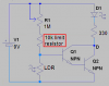
ok... it works but i would like it to come on when it is darker than what it does now (stronger resistor) i used a 100k pot, i would also like it to be brighter (i used a normal, small bulb)
Didn't you use a 2V red LED? Is the 9V battery new? The 330 ohm resistor sets its current to about 19mA. replace it with 220 ohms and it will be as bright as it can be at 29mA without burning out. If it still isn't bright enough then get a brighter LED.
ah thanks, i took away the pot and added a 1m resisor and that is ok, but i will try what you said because i wanted it to be adjustable, no i used a normal bulb, i'm going to replace it with a white LED or an orange one
Sorry, I edited my post after you saw my error.
You are correct, you needed more resistance than the pot. If you want it adjustable then use a 1M pot.
A white LED has a higher forward voltage than a red one so the 330 ohm current limiting resistor should be 180 0hms. If the orange LED is 2V then use 220 ohms.
i wondered where the diagram had gone lol, can't i use a resistor and a pot in series then? i thaught this would just lower the range of ajustability if that makes sense
i wondered where the diagram had gone lol, can't i use a resistor and a pot in series then? i thaught this would just lower the range of ajustability if that makes sense
ok, thanks..... i was gunna say is it possible for transisters to blow up? because mine were getting REALY hot, seems to be alright now that i have it working :roll: lol..... oh yes, the problem was the base of the 1st transistor was soldered 1 hole down on the stripboard
Of course transistors will burn out if too much current flows through them. You replaced R1 in the original circuit with a pot. When you turned down its resistance to zero then all the current from the battery flowed through the input of the trasistors, causing them to heat. Your transistors or pot might be damaged.
Soldering a joint takes only 2 seconds so it is unlikely that soldering will damage a transistor, unless your soldering iron is too hot.
well i was actualy trying to remove solder that was overlaping 2 tracks with just a soldering iron and there was a wire in the way somewhere so this made it harder, it took about 10-15 seconds with a 20w iron but i know now it's not the transistor because i tool it out to test it on my multimeter and it works (the 2nd one) however, i do not have the 1m pot yet so i've just got a 10k resistor and joined the 2 wires together that are suposed to go to the pot and the bulb is just VERRY dim all the time (just a part of the fillament is orange)
its not the bulb because when i connect it direct to the battery it works ok (this rules out the battery aswell)
The 330 ohms resistor in the circuit is designed to limit the current for an LED, not a light bulb. Remove it and if the light bulb's current is within the rating for your transistors then it should light to almost max brightness.
What are the part numbers of your transistors and light bulb?
Do you have a picture of the transistors from their datasheet so you are certain which of their wires is emitter and collector?
You should have a solder-sucker tool to remove solder. Cheap ones are just a rubber bulb that you squeeze, put the nozzle up against the melted solder to be removed then release the squeeze for it to suck. Better ones have a spring driven piston. My aluminum one must have been used thousands of times during its long life. Their nozzles are nylon or telflon that melts if your soldering iron is too hot. The solder is melted for only 1 second or less. I can remove an IC with 14 pins in less than 15 seconds. :lol:
i didnt use the 330 ohm resistor.......
i decided to strip it and start again, i tested BOTH transistors and one of them didnt work so i replaced it with a different one and it still doesnt work, it just comes on at normal brightness, the light doesnt affect it.
The transistor numbers are: CDIL BC108 (origonal) and CDIL BFY51 (replaced one)
Since you have only 10k instead of a 1M pot or resistor, it will take an extremely bright light shining on the LDR to turn off the transistors.
Just think about how an LDR works: the brighter is the light then the lower is its resistance. You might not be able to find a light that is bright enough.
Try it with a 1M or more resistor and I'll bet it shuts-off with moonlight!
This site uses cookies to help personalise content, tailor your experience and to keep you logged in if you register.
By continuing to use this site, you are consenting to our use of cookies.