Continue to Site

Welcome to our site!

Electro Tech is an online community (with over 170,000 members) who enjoy talking about and building electronic circuits, projects and gadgets. To participate you need to register. Registration is free. Click here to register now.

  • Welcome to our site! Electro Tech is an online community (with over 170,000 members) who enjoy talking about and building electronic circuits, projects and gadgets. To participate you need to register. Registration is free. Click here to register now.

Simple LED circuit turned nightmare. Help needed

Status
Not open for further replies.

EdStraker

Member
I set up what I thought would be a simple circuit for a diorama and for 4 days already been driving me up the wall.
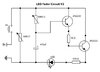
Circuit Outline:
It's function is to light 2 LED's (preferable 1-6 LED's) at consistent brightness (full or near full brightness).
When power is applied, the LED's need to charge up (slowly glow) to full, when power is removed, slowly fade off.
About 2 sec. charge up, 2 sec. fade out.

The problem with all iterations of this circuit I have tried is that it never achieves complete power discharge at the LED(s) and I can't seem to overcome the problem.
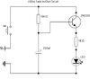
Have tried with and without a Transistor, With 2 Transistors, no joy.

Can anyone supply insight as to where I am going wrong?

This is the last version of a "working" circuit where I left off.

Thanks in advance, Rob
 

Attachments

  • led_fade_schematic.jpg
    led_fade_schematic.jpg
    649.5 KB · Views: 262
Add a high value resistor across base-emitter on the transistor, or across the cap.
100K may be OK.
 
The circuit you posted should go from black to light slowly. When the switch is opened the LED will go to black very fast. Is that what you see?
it never achieves complete power discharge at the LED(s)
Are you seeing a very very dim light for a long long time? after the switch opens
-----------------------------
I see it. The capacitor is discharging through the B-E of the transistor down through 1K, LED to ground. Interesting. Add a 1k as shown. Value not critical.
1628636325296.png
 
Last edited:
hint: disconnect the collector of the transistor from the resistor, and connect it to the +9V side of the switch...

btw the UFO reference is pretty cool... i used to watch that show back in the 1970s when i was a teenager.
 
Thanks to rj and Ron, I'll try these solution and let you know. It doesn't have to be this circuit in particular, it's just were I stopped tinkering. If anyone has a better solution I am sooo open to it at this point as long as it meets the posted requirments.

@unclejed: Yeah, lol....I became in instant fan when I was a little kid. But, still a Trekkie to the core :)
 
Ok, so I had to re-engineer it a little further. Ron's solution worked out but there was issues with more than one LED. To compensate for this I added another Transistor to provide a constant current source (sort of) to the LED's and replaced the static resistors with 100k pots to fine tune the charge and discharge times. The only thing that is of any concern is the 1k resistor between the 2 Transistors. Does this look ok to you guys or should it be increased a bit?


I did see that as well as another version similar to it about a year ago. The problem there is the circuit needs to be pre-powered before the switch is thrown otherwise it doesn't work correctly. I needed something that would function with or without a switch when power is applied. Thanks for the heads up though.
 

Attachments

  • led_fade_schematicV2.jpg
    led_fade_schematicV2.jpg
    95.9 KB · Views: 226
The only thing that is of any concern is the 1k resistor between the 2 Transistors.
The two transistors form a Darlington-connected emitter follower. No base current limiting is needed for either transistor.

Please add reference designators to the schematic so we can be clear about which transistor does what.

ak
 
rjenkinsgb I just tried that config and oddly enough, it doesn't seem to matter. The circuit still functions the same except for an ever so slight delay in initial charge up. I'm a bit lost on that one.

@ak: refer to post #7
The 1k resistor was on the original schematic I found before I modified it. Didn't say what it was for.
 
Do you want this as the charge discharge curves ?

1628766664880.png


Regards, Dana.
 
Last edited:
A case to be made for a processor solution.

1) You want the ramp linear up and down. Exponential ramps have this
quick drop and slow extinguish, don't look quite right. PWM in processor
a natural to do this.

2) You need to be able to detect "brownout" condition on power, again a
processor with A/D handles that nicely, and some code setting flags.

3) You need recovery, power flickers, triggering ramp down, but then is
restored, so ramp down should be terminated and ramp from there up
started. And vice versa of course. This is code and use of A/D.

4) You need to completely extinguish LED, no residual "glow". Todays LEDs
have a glow at low uA levels. Again a PWM takes decay all the way to shutoff.

5) When power is lost you need a cap large enough to hold up the processor
and supply power for LEDs as they turn off. Thats easily calculated.

An Arduino nano board would do this handily. Use this to do dev, and then
possibly program 8 pin dip ATTINY85 to do this. One part + LEDs + R's for LEDs.
You might need an external transistor to handle enough current for all 6 leds.

Just a thought.


Regards, Dana.
 
Last edited:
Here is basic solution using Nano

1628797807855.png


The code looks lengthy buts is mostly two duplicate routines, to inc a number used to set PWM duty
cycle to ramp up, the other routine to decrement it for ramp down.

A/D is used to sense power supply, and a bulk cap would keep processor running long enough to do the ramp
down before it stops running.

Zip file is board video running a loop ramping up and then down. It has a nice clean linear ramp. Note
human eye is actually log to brightness, so maybe with some effort the discrete version you are working
on will work out. Core of that is a bulk cap that has to supply LED current, and I would think since your
drive is a RC exponential that you would want to build a V controlled current source for the LEDs. That
way the LED driver will be feed an exponential, and the linear current source transforms that exponential
V to an exponential current maintaining the exponential behavior. By using a current source you could also
series the 6 LEDs, but need a higher V to do the design for a supply. 9V batter may not be enough.


Regards, Dana.
 

Attachments

  • IMG_0310.zip
    13 MB · Views: 152
Last edited:
Thanks to all that helped out. Problem solved sort of. The circuit functions as required but I have to deal with a longer delay in initial charge up time if the circuit is completely discharged for a longer period of time. The addition of the 100k VR in place of the 1k resistor is the solution I have gone with in this case.
 
Status
Not open for further replies.

Latest threads

New Articles From Microcontroller Tips

Back
Top