Continue to Site

Welcome to our site!

Electro Tech is an online community (with over 170,000 members) who enjoy talking about and building electronic circuits, projects and gadgets. To participate you need to register. Registration is free. Click here to register now.

  • Welcome to our site! Electro Tech is an online community (with over 170,000 members) who enjoy talking about and building electronic circuits, projects and gadgets. To participate you need to register. Registration is free. Click here to register now.

Simple LED Analog Clock Idea

For The Popcorn

Well-Known Member
Most Helpful Member
As one of the members here struggles with an LED analog clock project, an idea for a simple LED clock design came to mind. This is somewhat similar to my servo Clock For Geeks idea. Usually, when you look at a wall clock, you don't need to know the exact time. "About" is close enough. On my servo clock, resolving quarter hours was easy but it could be read fairly accurately.

LEDs don't easily replicate the hands of an analog clock, at least without a multitude of them. Following the theme of my analog clock, an easy-to-understand "about" clock is pretty simple. A ring of 60 LEDs (60 to preserve the ability to display minutes, but 48 works better for this idea) displays not minutes, but hours. As the hours progress from noon to midnight, the ring is progressively illuminated (and repeated from midnight to noon). The ring of LEDs can be controlled by eight 74HC595 shift registers.

Inside the ring of 60 (or 48) LEDs are 12 LEDs to indicate the hour positions. These LEDs will always be illuminated, probably dimmer than the outer ring. To maintain flexibility, I would operate these 12 LEDs from two separate 74HC595s, with the enable input controlled by a pwm pin.

So why didn't I post that in the existing thread? That thread has reached 20 pages and the member is still lost in the woods. I didn't want to provide further distraction or have this idea buried in the weeds.

servo clock.jpg
Servo Clock - Yes. Yes It Does Indicate 4:20
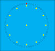

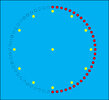
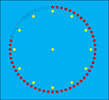
noon.jpg
Noon

1-36.jpg
1:36

6-00.jpg
6:00

9-24.jpg
9:24
 
Last edited:
64 bit SR in one part, but not much other I/O left. Could do a muxed matrix to get
around that, that then would allow all the other analog and digital stuff on this part
to be used.

Part does have RTC in it....but non muxed I dont think enough I/O to add xtal....

1750463385686.png


Was done with simple Verilog code, could have been done just with schematic capture
in the tool.

Code:
//`#start header` -- edit after this line, do not edit this line
// ========================================
//
// Copyright YOUR COMPANY, THE YEAR
// All Rights Reserved
// UNPUBLISHED, LICENSED SOFTWARE.
//
// CONFIDENTIAL AND PROPRIETARY INFORMATION
// WHICH IS THE PROPERTY OF your company.
//
// ========================================
`include "cypress.v"
//`#end` -- edit above this line, do not edit this line
// Generated on 06/08/2021 at 10:16
// Component: Shift64
module Shift64 (
    output [63:0] dataout,
    output  serout,
    input   clkin,
    input   clrall,
    input   loadall,
    input   serin,
    input   setall
);
    parameter InitPatt = 0;

//`#start body` -- edit after this line, do not edit this line


//    wire [63:0]paraout64;
    reg  [63:0] sreg;                              // actual register

    assign dataout = sreg;
    assign serout = sreg[0];
   
    // reset and load are both syncronous
    always @ (posedge clkin )
   
    begin
   
        if (clrall == 1'b1)                         // clear / reset has precedence
   
            sreg <= 64'h0000000000000000;
       
        else
       
        if (setall == 1'b1)
       
            sreg <= 64'hFFFFFFFFFFFFFFFF;           // set shift reg to all 1's
       
        else
       
        if (loadall == 1'b1)                        // Load user preset/config data
       
            sreg <= InitPatt;
           
        else
       

            sreg <= { serin, sreg[63:1] };          // Do a one bit shift and take in SerIn bit
   
    end

//`#end` -- edit above this line, do not edit this line
endmodule
//`#start footer` -- edit after this line, do not edit this line
//`#end` -- edit above this line, do not edit this line
 
Last edited:
My preferred weapon of choice is Swordfish Basic and PIC18F-series chips. In fact, the servo clock was what got me started with microcontrollers.

The full version of Swordfish Basic has recently been made available free of charge by its developer. Swordfish is a fast compiled Basic supporting all PIC18F devices. tumbleweed is instrumental in keeping Swordfish up to date with the latest devices. His talents are greatly appreciated.

The suggestion to use 74HC595s comes from a project in the aforementioned thread by Beau Schwabe to make a large diameter analog clock/general purpose display from segments using cheap Chinese boards. He posted a couple amazing videos showing the '585s in action.

Beau Schwabe's MQTT Analog Clock / VU Meter / Multipurpose Display
 
Last edited:
As one of the members here struggles with an LED analog clock project, an idea for a simple LED clock design came to mind. This is somewhat similar to my servo Clock For Geeks idea. Usually, when you look at a wall clock, you don't need to know the exact time. "About" is close enough. On my servo clock, resolving quarter hours was easy but it could be read fairly accurately.

LEDs don't easily replicate the hands of an analog clock, at least without a multitude of them. Following the theme of my analog clock, an easy-to-understand "about" clock is pretty simple. A ring of 60 LEDs (60 to preserve the ability to display minutes, but 48 works better for this idea) displays not minutes, but hours. As the hours progress from noon to midnight, the ring is progressively illuminated (and repeated from midnight to noon). The ring of LEDs can be controlled by eight 74HC595 shift registers.

Inside the ring of 60 (or 48) LEDs are 12 LEDs to indicate the hour positions. These LEDs will always be illuminated, probably dimmer than the outer ring. To maintain flexibility, I would operate these 12 LEDs from two separate 74HC595s, with the enable input controlled by a pwm pin.

So why didn't I post that in the existing thread? That thread has reached 20 pages and the member is still lost in the woods. I didn't want to provide further distraction or have this idea buried in the weeds.

View attachment 150180
Servo Clock - Yes. Yes It Does Indicate 4:20


View attachment 150179
Noon

View attachment 150176
1:36

View attachment 150177
6:00

View attachment 150178
9:24
Have you seen the Amazon Alexa clocks?.
 
I have not. Am I missing something?
 
A ring of 60 LEDs (60 to preserve the ability to display minutes, but 48 works better for this idea) displays not minutes, but hours. As the hours progress from noon to midnight, the ring is progressively illuminated (and repeated from midnight to noon).

One of my fellow electronics fanatics from School wanted to build something like that, back in the mid 70s, though as far as I know he never completed it.

His idea was pretty much the same for the hours part, though with one led flashing for the minutes, if I remember right.
He did initially want to make the hour ring alternate between illuminating progressively then going off progressively, but realised it's too confusing.

I think it was based on something from a TV program or movie?
 
I have not. Am I missing something?
It's a regulator analogue style clock, with hands and numbers - then there's 60 white LED's around the edge. The hands are driven by a (stepper?) motor, and adjust themselves - the LED's are used to display the timer settings, and count them down. They count down a minute at a time, then for the last minute switch to one a second. If you've got multiple timers set those are shown by a single bright LED.

I've got two, they are really useful - I use the timers a LOT :D
 
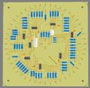
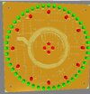
I worked on this design today - it's almost finished. I used 48 LEDs in the ring to represent 15 minute intervals. At 12:00, the top LED will be illuminated. Every 15 minutes adds another LED. This will be a very glanceable presentation to tell you if it's time to get going.

The inner ring of LEDs are hour markers to aid in reading the clock. I anticipate they will always be illuminated, but they are all individually controllable if you'd like to do it differently. The four center LEDs might be animated to show seconds.

I've designed this as an SPI peripheral so any micro can be attached to control it. I've left room in the center so a micro could be added to the board if desired. I used through-hole resistors and LEDs to make the board easy to assemble for more people.

I'll provide more details on Jon's Imaginarium. I'll make the Gerber files and EasyEDA files available by request. Send me a message at Jon's Imaginarium if you'd like the files.

Schematic_Simple LED Analog Clock.png


pcb - front.jpg


pcb - back.jpg
 
Last edited:
A minor nit.

I would go with only one orientation for all resistors. Consider one or two vertical columns of shift registers down the center of the board, and two vertical columns of 30 resistors each outside the shifters; very much like your schematic layout. This will make things easier to understand, construct, and debug. I don't normally recommend having the schematic be the physical layout, but in this case it fits very well.

ak
 
Last edited:
I made a somewhat similar clock, but with just 12 bi-color LEDs. A red LED indicates the hour, a green LED indicates the nearest minutes position (+/- 2.5 minutes), and a Yellow LED indicates that the same LED is used for both hour and minute.
 
A minor nit.

This layout is working pretty well for me and the arrangement is pretty clear to follow. I want to leave as much open space in the middle to preserve the option of adding a micro directly on the board.

For ease of programming, I opted to control the 49 "minute" LEDs (really quarter-hour LEDs) with the first six '595s, and the hour & center LEDs with the final two '595s. That makes routing a little messier, but should make any animations easier. It also allows controlling the brightness of the two groups of LEDs easier (using PWM on the /OE pins, instead of sending a crap ton of data).

Appreciate your comments.
Have you thought of using WS2812 Neopixels?, and it makes the board much simpler as well.
 
Certainly neopixels would have been an option. But I wanted to do this on the quick&dirty, cheap, easy to assemble, easy to code for.

And yes, it's partially in response to a certain member here who has been struggling to make an "LED clock" for nearly ten months who still does not understand how shift registers are used. He believes the ultimate LED clock will have exactly two LEDs illuminated at any time, one for minutes and one for hours, which will be a totally unintelligible representation of time.

Yes, sometimes I can be pretty petty. I have spent too many years of my life and hours of my time trying to help this guy, and he's learned absolutely nothing.
 
I have a digital clock design that I built not too long ago with the 60 seconds around the ring. No mirco-computer or programming necessary. I used 2 CD4017 IC's and 6 resistors in a 60 LED matrix, driven by a 1 Hz pulse. This could probably be modified for other uses.
 

Latest threads

Back
Top