Continue to Site

Welcome to our site!

Electro Tech is an online community (with over 170,000 members) who enjoy talking about and building electronic circuits, projects and gadgets. To participate you need to register. Registration is free. Click here to register now.

  • Welcome to our site! Electro Tech is an online community (with over 170,000 members) who enjoy talking about and building electronic circuits, projects and gadgets. To participate you need to register. Registration is free. Click here to register now.

Simple IR Transmitter and Receiver

Status
Not open for further replies.
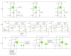
I have created a circuit diagram for my car. Does it look about right? I have annotated it to make it easier to see what is going on.

Do you reckon the solenoids are an appropriate choice for the steering mechanism? And will all the components be able to cope with up to 43kHz?

Thanks for your time :)
 

Attachments

  • RC Car Schematic.png
    RC Car Schematic.png
    90.3 KB · Views: 164
Radio control uses a pulse width to move a servo. the pulse width is variable and the movement of the servo is also variable. Not simply on and off.

Your odd idea uses detection of different frequencies.
Your bandpass filters will work poorly because they are not sharp and attenuate the wanted frequency. Look in Google for a Multiple Feedback Bandpass Filter using a single opamp that can have a very sharp bandpass with no attenuation of the wanted frequency.

Your very simple highpass filter is overloaded by the very simple lowpass filter. The filters seriously overrlap. Then they attenuate the wanted frequency.

Because the filters are very simple then they have a gradual slope of only 6dB/octave. 19khz in the 19khz filter is attenuated about 10 times. 9.5kHz and 38khz are down to only half the level of 19kHz.
 
Ok, clearly I am not getting anywhere with my design (as kindly expressed by Nigel :p)

I did some googling and forum searching and found a receiver diagram.

From http://english.cxem.net/guard/guard29.php

If you can understand the diagram, can you tell me how to adjust any components to change the filter to receive a frequency. Does this make sense?
 

Attachments

  • guard29-2.gif
    guard29-2.gif
    4.3 KB · Views: 145
can you tell me how to adjust any components to change the filter to receive a frequency
Well, as none of the components shown have known values that's tricky! As I read the circuit it doesn't even have a filter. It seems to be just an amp triggering a 555 or similar.
 
The schematic you found is a defective project at www.aaroncake.net . The parts list is there.
The lousy old 741 opamp is missing a resistor to a reference voltage (half the supply voltage) for its input pin3 so it probably does not work.
I don't know if the LM567 frequency detector is designed properly.
 
Thanks audioguru, I was not sure, and did not want to waste my time building a circuit like that.

If you know of a working IR transmitter/receiver schematic online, it would save me some time. Thanks for your help.
 
There are AirHogs remote controlled model helicopters, airplanes and cars that use IR signalling. They steer smoothly and proportionally, not Bang-Bang full left, center or full right like your extremely simple idea. Their motor speed control is also proportional for any speed not Bang-Bang full power or no power like your extremely simple idea.
 
Sorry, there is some miscommunication going on here...

Do you know of any SCHEMATICS for an IR receiver? And yes, I have given up my simple idea.
 
I don't know of a schematic of an IR receiver for a remote controlled model car. The simple one you found might be fixed and can use a more modern opamp.
A simple IR receiver IC is used in many electronic products but it works with data from the transmitter and works poorly when it receives simple continuous IR (because it thinks it is receiving interference from a compact fluorescent light bulb).
 
Status
Not open for further replies.

Latest threads

Back
Top