Hey,
This winter break I'd like to finally site down and make a distortion pedal for my guitar, mainly because I would like one and the knowledge to make them.
So over the past few months I've been looking at using transistors on and off from a number of sources. But none of them have really helped me for some reason.
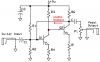
The idea is to make one similar to the old fuzz-face pedals, but with NPN Silicon transistors (or MOSFETs???).
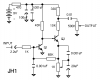
Attached is a basic schematic that I have drawn up (it's almost identical to the fuzz-face pedals.)
Now what I actually want to know from you guys is:
-How should I go about choosing transistors?
-How do I go about choosing resistor values for the transistors?
-What is the input voltage from a Guitar (I've got Humbuckers so they are pretty high gain). I've heard that 500mV is a reasonable figure to use?
-What kind of gain should I be going for?
-Should I even be biasing the first transistor to get the sound I want? (aka Fuzz-Face)
-Is my coupling capacitor pointing in the right direction?
-Is 100uF a reasonable value for the supply capacitor? If I were to use a battery.
-How do I find out what kind of values I should use for the coupling capacitors? My guess is that I use 1/(2(pi)f) where f is the lowest frequency the guitar could produce. And should they both be the same value?
-Do I need to add any capacitors in parallel around the emitter resistors?
-Do I need a resistor before the first transistor?
-If I were to add a pot along the negative feedback path would kind of value should I go for? Does this control gain?
-Would 50k be a reasonable value for P1?
And please don't just tell me the answer I would really like to know why it is I am doing something so that I can have an understanding of the subject.
Thanks for any help or suggestions in advance,
Trevor
(PS: I'm not doing this for homework I assure you, I'd just like to learn a bit before second year engineering in which I'll actually start this kind of stuff.)
This winter break I'd like to finally site down and make a distortion pedal for my guitar, mainly because I would like one and the knowledge to make them.
So over the past few months I've been looking at using transistors on and off from a number of sources. But none of them have really helped me for some reason.
The idea is to make one similar to the old fuzz-face pedals, but with NPN Silicon transistors (or MOSFETs???).
Attached is a basic schematic that I have drawn up (it's almost identical to the fuzz-face pedals.)
Now what I actually want to know from you guys is:
-How should I go about choosing transistors?
-How do I go about choosing resistor values for the transistors?
-What is the input voltage from a Guitar (I've got Humbuckers so they are pretty high gain). I've heard that 500mV is a reasonable figure to use?
-What kind of gain should I be going for?
-Should I even be biasing the first transistor to get the sound I want? (aka Fuzz-Face)
-Is my coupling capacitor pointing in the right direction?
-Is 100uF a reasonable value for the supply capacitor? If I were to use a battery.
-How do I find out what kind of values I should use for the coupling capacitors? My guess is that I use 1/(2(pi)f) where f is the lowest frequency the guitar could produce. And should they both be the same value?
-Do I need to add any capacitors in parallel around the emitter resistors?
-Do I need a resistor before the first transistor?
-If I were to add a pot along the negative feedback path would kind of value should I go for? Does this control gain?
-Would 50k be a reasonable value for P1?
And please don't just tell me the answer I would really like to know why it is I am doing something so that I can have an understanding of the subject.
Thanks for any help or suggestions in advance,
Trevor
(PS: I'm not doing this for homework I assure you, I'd just like to learn a bit before second year engineering in which I'll actually start this kind of stuff.)