Continue to Site

Welcome to our site!

Electro Tech is an online community (with over 170,000 members) who enjoy talking about and building electronic circuits, projects and gadgets. To participate you need to register. Registration is free. Click here to register now.

  • Welcome to our site! Electro Tech is an online community (with over 170,000 members) who enjoy talking about and building electronic circuits, projects and gadgets. To participate you need to register. Registration is free. Click here to register now.

Simple control for injector pulse duration

Status
Not open for further replies.

malc9141

Member
Hello

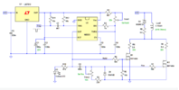
I have asked about this previously. Forgive me for asking again! Some years back, a helpful member simplified a design for me - as shown below. It has come in for criticism but it worked OK. Then it stopped working. I could not find a fault.
Can an expert please see if it looks right? Someone here said the RC timing design was wrong.

It should get one input pulse, and two simultaneous output pulses, one brief, one longer (each able to be varied). Thus, the brief one yields double the voltage of the longer one. Please confirm that the output duration is independent of the input pulse duration.

Thanks

Malc
 

Attachments

  • Screen Shot 2023-02-15 at 2.02.01 pm.png
    Screen Shot 2023-02-15 at 2.02.01 pm.png
    219.1 KB · Views: 158
Solution
However, if I just put an ( 0.1 ms) RC line to 0v from the optosensor, it should deal with the problem. The problem was, using an optosensor, you need a small reflective area - and if this moved slowly past the optosensor, it would start to increase the time of the pulse.
I don't understand? My pulse circuit doesn't have an opto-sensor and was designed to have a sharp negative-going input pulse.
If you need to have the 555 respond to a very slowly changing input signal (not part of the original design brief) then the input stage of my circuit would require modification to include a Schmitt trigger.
How much do you know about micro-processors?
Not my field of expertise, although I have played with one or two.
Hi. That's a circuit I designed. Simulation confirms the output pulse widths are independent of the input pulse width as long as the input pulse exceeds a minimum of a few microseconds and is less than the required pulse repetition period.
Regarding the timing criticism, R3 could be increased to, say, 2k2 to make the setting of the Trim2 pot less critical to adjust for brief Fire pulses. All timings might need adapting to suit various injectors.
Then it stopped working.
In what way? Missing pulse? Wrong timing? Voltages wrong/absent? .....?
 
Last edited:
Hi Alec Yes of course I know you! Many thanks for popping up. I am much reassured.

Someone on the board here said the RC wasn't RC at all. But I don't understand the 555 so thought maybe, just maybe, I had missed something.
What went wrong? It just stopped responding to the pulse from your little Input Box, I did not have enough knowledge to understand. Then an expert (truly) added some bits and now it follows the set RC time only if the input signal is briefer. Thats no use because as the signal slows, the input lasts longer!

I could make another complete.

But let me ask something else: my expert friend says I should use a programmed circuit. He quickly made an Arduino system but I haven't tried it. My general Q now, is (as in a car, say), do you know how a computerised circuit could be made.

All good wishes

Malc
 
Someone on the board here said the RC wasn't RC at all.
'RC' in relation to the circuit means Resistance x Capacitance. 'RC' can also stand for Remote Control. Perhaps that was what the someone had in mind?
Then an expert (truly) added some bits and now it follows the set RC time only if the input signal is briefer.
Ask the expert what was added and where. A schematic of the modiication would be helpful.
Briefer than what?
He quickly made an Arduino system but I haven't tried it.
Well, if it has been designed by your expert it should do the job. Try it.
My general Q now, is (as in a car, say), do you know how a computerised circuit could be made.
A microcontroller (such as an Arduino) would be programmed with timing information and interfaced to input and driver circuits.
 
When he changed things, he did explain but it was too subtle for me. However, if I just put an ( 0.1 ms) RC line to 0v from the optosensor, it should deal with the problem. The problem was, using an optosensor, you need a small reflective area - and if this moved slowly past the optosensor, it would start to increase the time of the pulse. I do not understand why his modification could possibly affect the 555 output, but it did. Sometimes, "clever" people are a bit too clever.
Of course I will try the Arduino but for practical reasons, I want to sell the single cyl prototype and would do so with the (your) Control. So I want that to be OK.

How much do you know about micro-processors? More industrial types than Arduino.
 
However, if I just put an ( 0.1 ms) RC line to 0v from the optosensor, it should deal with the problem. The problem was, using an optosensor, you need a small reflective area - and if this moved slowly past the optosensor, it would start to increase the time of the pulse.
I don't understand? My pulse circuit doesn't have an opto-sensor and was designed to have a sharp negative-going input pulse.
If you need to have the 555 respond to a very slowly changing input signal (not part of the original design brief) then the input stage of my circuit would require modification to include a Schmitt trigger.
How much do you know about micro-processors?
Not my field of expertise, although I have played with one or two.
 
Last edited:
Solution
When he changed things, he did explain but it was too subtle for me. However, if I just put an ( 0.1 ms) RC line to 0v from the optosensor, it should deal with the problem. The problem was, using an optosensor, you need a small reflective area - and if this moved slowly past the optosensor, it would start to increase the time of the pulse. I do not understand why his modification could possibly affect the 555 output, but it did. Sometimes, "clever" people are a bit too clever.
Of course I will try the Arduino but for practical reasons, I want to sell the single cyl prototype and would do so with the (your) Control. So I want that to be OK.

How much do you know about micro-processors? More industrial types than Arduino.

An Arduino isn't a micro-processor (or even a micro-controller), it's a development system using a variety of different processors, although the original ones used Atmel (now MicroChip) AVR processors. In comparison, an Arduino is 'similar' to a Commodore 64 (a complete computer), rather than just the chip (a 6502 micro-processor in the C64's case, or an Atmel 328 micro-controller in the original Arduino)

Nothing wrong with using an AVR processor, but the most popular ones tend to be MicroChip PIC devices, which are found in an incredible variety of applications.

You could easily develop your design on an Arduino, and then build the final product using a bare 328 processor (and supporting components). Likewise, you could do the same with a MicroChip PIC development board, and then transfer the final product to your own board using a PIC. Many PIC's have the advantage of internal oscillators, so don't require fragile crystals, as long as maximum accuracy isn't required (and it rarely is).
 
Status
Not open for further replies.

Latest threads

New Articles From Microcontroller Tips

Back
Top