Continue to Site

Welcome to our site!

Electro Tech is an online community (with over 170,000 members) who enjoy talking about and building electronic circuits, projects and gadgets. To participate you need to register. Registration is free. Click here to register now.

  • Welcome to our site! Electro Tech is an online community (with over 170,000 members) who enjoy talking about and building electronic circuits, projects and gadgets. To participate you need to register. Registration is free. Click here to register now.

sim-op amp-closed loop frequency response in LTSWcad3

Status
Not open for further replies.

Electricman2K5

New Member
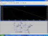
Hi does anyone know how to simulate te closed loop frequency response for an op-amp in LT switcher cad 3. Ive tried using the cct below and i can only seem to get the open loop response.(the program ignores the feedback components) I also want to find the 3db frequencies the design is for a microphone amplifer.

thanks
 

Attachments

  • sim_464.jpg
    sim_464.jpg
    100.9 KB · Views: 634
Hi Electricman,
The max gain will be 1+(100k/4.7k) = 22.3.
The datasheet shows the upper -3dB frequency at about 120kHz. It will be even higher with reduced gain settings, but the opamp can't swing its output fully above 100kHz.
C3 and R4 will cause a -3dB low frequency cutoff at 1.55Hz (kinda low, eh?) and the input and output capacitors will react with the source and load impedances which might cause the lower -3dB frequency to be much higher.
Never mind the darn sim. :lol:
 

Attachments

  • tl071_response.gif
    tl071_response.gif
    17.5 KB · Views: 614
It is open loop because of the varistor connections
 

Attachments

  • ltspiceamp.gif
    ltspiceamp.gif
    18.3 KB · Views: 584
Hi Fried,
Good, the sim works with a real 100k resistor instead of a varistor surge arrester. I was wondering why it looked odd.
It has a 9V supply, a 0.5VAC input and a gain of about 22.
The input is 1.414Vp-p and therefore the output is 31Vp-p.

How does the sim's opamp get 31V output from a 9V supply?
Will it still produce a 31V output without a supply? :lol: :lol:
 
audioguru said:
Hi Fried,
Good, the sim works with a real 100k resistor instead of a varistor surge arrester. I was wondering why it looked odd.
It has a 9V supply, a 0.5VAC input and a gain of about 22.
The input is 1.414Vp-p and therefore the output is 31Vp-p.

How does the sim's opamp get 31V output from a 9V supply?
Will it still produce a 31V output without a supply? :lol: :lol:
What op amp model are you using?
 
The universal opamp has a bandwidth much higher than an old 741.
 
The SwCAD universal op amp can be set up to look approximately like almost any op amp. To make it look like National's LM741, right-click on the universal op amp symbol and change the parameters. The following setup works pretty well for the circuit above.

SpiceModel level3a
Value
Value2 Avol=200k GBW=1Meg Slew=312k
SpiceLine ilimit=25m rail=1 Vos=0 phimargin=70
SpiceLine2 en=0 enk=0 in=0 ink=0 Rin=500Meg


I didn't play with ilimit or the noise params. The universal model doesn't handle recovery time from overdrive, nor does it seem to handle Rin very well (it makes no distinction between common mode Rin and differential mode Rin).

Ron

PS for AC analysis (Bode plots), you need to set the AC input to 1 volt. As with any version of Spice that I'm familiar with, the model is linearized before AC analysis, so you can't overdrive it. If you use other than 1 volt input, you have to scale the gain accordingly. For example, a 0.1V signal will plot as -20dB, a 0.5V signal will plot as -6dB, etc.
 
Status
Not open for further replies.

Latest threads

New Articles From Microcontroller Tips

Back
Top