Continue to Site

Welcome to our site!

Electro Tech is an online community (with over 170,000 members) who enjoy talking about and building electronic circuits, projects and gadgets. To participate you need to register. Registration is free. Click here to register now.

  • Welcome to our site! Electro Tech is an online community (with over 170,000 members) who enjoy talking about and building electronic circuits, projects and gadgets. To participate you need to register. Registration is free. Click here to register now.

Signal indicator circuit tweaking help

Status
Not open for further replies.

diy didi

Member
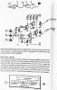
I have built the attached circuit into an existing 5 channel mixer project.
It monitors by way of 2 led’s the signal level present at the output of the mixer.
It minitors L&R outputs with two adding diodes at its input.
My question is. I would like to double its sensitivity instead of the first Led turning on at 2V, i would like to have it switch on at 1V of input, and the red led at 2,5V of input.
Which components should be changed? I was thinking change all diodes to Schottky perhaps?
Thanks in advance.
 

Attachments

  • 12C8E2F1-43E9-43C7-BF53-0CA5973CA056.jpeg
    12C8E2F1-43E9-43C7-BF53-0CA5973CA056.jpeg
    810.7 KB · Views: 204
Change just the three input diodes to schottky types to increase overall sensitivity slightly.

D5 is used to put a negative offset on the emitter of T2, reducing the base voltage (to ground) needed to turn it on.
That does not want decreasing.

Changing D4 would increase the sensitivity of the second LED a bit more.

You could add very low gain buffer amps to the input to increase sensitivity further. It would also isolate the diodes from the real audio path, where they may be causing distortion or DC offsets.
 
You can still get germanium diodes 1n34, whuch turn on at 0.3v.
 
a way to detect a preamp stage being overloaded is to monitor the output and try to detect the signal approaching a power supply voltage, or to detect gross changes in the waveform (such as you would get with the signal being clipped). the circuit shown in the OP only detects one half of the waveform, and with actual music or speech, the waveforms are far from symmetrical in real life... something about doing a "diode or" in an audio system seems unnatural to me, maybe if there were buffer amps as rjenkinsgb mentioned, it might not look like a train wreck. something similar to a clipping indicator circuit used for power amps maybe, but those are usually used with an amplifier with fixed gain (usually a differential amp, as long as the input and output waveforms are similar and proportional, there's little output, but if the signal is clipped, the two inputs are different, which appears as spikes on the output of the detector), and preamps with volume and tone controls are anything but fixed gain.
 
Last edited:
Status
Not open for further replies.

New Articles From Microcontroller Tips

Back
Top