Continue to Site

Welcome to our site!

Electro Tech is an online community (with over 170,000 members) who enjoy talking about and building electronic circuits, projects and gadgets. To participate you need to register. Registration is free. Click here to register now.

  • Welcome to our site! Electro Tech is an online community (with over 170,000 members) who enjoy talking about and building electronic circuits, projects and gadgets. To participate you need to register. Registration is free. Click here to register now.

shifting ADC VRef- for PIC16F876A

Status
Not open for further replies.

aljamri

Member
Hi,
I am trying to use ADC to read a signal of 4 to 20 mA. With the help from two superb ETO members in This Thread. , the software part is accomplished.

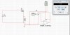
I've tested the circuit both using OshonSoft IDE and on a bread board using 0 to 5 volts (0 to 20mA) signal, The Vref- is connected to Vss (0v) and Vref+ to VDD (5V) . The circuit works as expected.

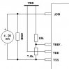
When I tried to shift the Vref- from 0v into 1v using two resistors as voltage divider between Gnd and 5V. The resistors were 10k and around 7.5k. Then applied the signal, (1 to 5V) into RA0, and it woks fine too.

THE PROBLEM:
When I tried to replace the input voltage with mA signal ( 4 to 20 mA ), and by using a 250 Ohm shunt resistor, the things went wrong, as I've connected the shunt resistor between the Gnd and AN0 ( as what I did in all the previous succeeded tests ).

I'm wondering what is wrong, is it where I have to connect the signal or something else.
 
Ah yes... A problem.. the 4 - 20 ma should also be referenced to 1v.. But if you connect the shunt resistor to 1V then it will no longer be 1V.. The best I can suggest (this is what I do ) is use a 1.2V reference chip (I don't think you can get a 1V reference chip)
 
Hi Ian,
Oh my God, I've read this once in Application Note (AN546) and thanked my god that what I thought that I'm not going to need them.

Anyway, in that there is no reference to 1V, they started by 3.3V using 1N746. Is there any way to overcome this problem, as if I ordered any part, it takes almost one month to get it.

If you're shifting the references for the A2D, have a good read of the datasheet, there are considerable restrictions on what you can do.

However, I would suggest doing the shift in your software - doing it in the hardware means you've no test for there been no connection, which is the point of the 4-20mA range (instead of 0-20mA)
 
Last edited:
hi aljamri
How did it go wrong.?

The 1V on -Vref, should make the adc ignore voltages below 1V

The 250R is correct from adc0 and 0V., it should have a voltage of 1 thru 5V for a loop current of 4 to 20mA.

The Span of the 1023 counts should be from 1V thru 5V.

Whats the problem.?

EDIT:
I assume that you programmed the PIC pins so that they are active as +/-Vref
EDIT:
**broken link removed** Originally Posted by ericgibbs **broken link removed**
You could remove the bottom end +1V offset in the program, give you a Span of 4V.
**broken link removed** Originally Posted by ericgibbs **broken link removed**
I would do it in software, its cheaper and 4V is good enough.:)
 
Last edited:
Here some thing to look at
 

Attachments

  • mA.jpg
    mA.jpg
    120 KB · Views: 174
  • Volts_like this.jpg
    Volts_like this.jpg
    113.6 KB · Views: 192
Hi everybody and very good morning for all of ETO members, I’m happy for two reasons.

First of all, that my thread attracts the attention of this number of ETO experts :) .

Secondly, that my problem has a software solution.
Before I start this thread, I remembered Eric said he would solve it in software, so I read a lot in its datasheet searching for port setting or alike ( remembering software reference in PIC comparators ) and found nothing in this regard except the attached part .

Thanks for all.
 

Attachments

  • A2D01.JPG
    A2D01.JPG
    80.3 KB · Views: 163
Here some thing to look at

Hi be80be,

Your pictures are O.K.

Amazing (for me at least) How do you get current reading while you've connected your Ammeter in parallel ??
 
Hi everybody and very good morning for all of ETO members, I’m Before I start this thread, I remembered Eric said he would solve it in software, so I read a lot in its datasheet searching for port setting or alike ( remembering software reference in PIC comparators ) and found nothing in this regard except the attached part .


Simply subract the 4mA reading from the actual reading in the code, it's only a couple of lines - it's nothing to do with the hardware or datasheet. You could also check if the reading is less than that minimum, which would signify an error - probably no connection somewhere.
 
The 1V on -Vref, should make the adc ignore voltages below 1V
The 250R is correct from adc 0 and 0V., it should have a voltage of 1 thru 5V for a loop current of 4 to 20mA. The Span of the 1023 counts should be from 1V thru 5V. Whats the problem.?
I don't know what happen, all of the sudden, when I connected the mA source, the LCD reads 00.00 and not change .

I assume that you programmed the PIC pins so that they are active as +/-Vref
I am not sure that I understood this, Burt (be80be) offered me the attached code and I used it with minor changes. How to know which is which.

green is be80be code
rest is me

Code:
[COLOR=seagreen]//char message1[] = "ADC Value= ";
[/COLOR] char *value = "00.00 %";
 unsigned int ADC_Value;
void main() {
  ADCON0 = 0b11000000;
  ADCON1 = 0b10001111;
  TRISA  = 0xFF;              // PORTA is input
  TRISB  = 0;                 // PORTB is output
  TRISC  = 0;                 // PORTC is output
  
  [COLOR=seagreen]//Lcd_Custom_Config(&PORTB,7,6,5,4,&PORTB,2,0,3);
[/COLOR]  Lcd_Init(&PORTB);           // Initialize LCD
 [COLOR=seagreen] //Lcd_Cmd(Lcd_CURSOR_OFF);    // Turn cursor off[/COLOR]
  do {
       adc_value = ADC_Read(0);
       PORTC = ADC_Read(0);
    [COLOR=seagreen]// value[0] = adc_value/1000 + 48; // Add 48 to get character value
[/COLOR]      value[0] = adc_value/100 + 48; // Add 48 to get character value
   
  [COLOR=seagreen]//  value[1] = (adc_value/100)%10 + 48;
[/COLOR]     value[1] = (adc_value/10)%10 + 48;
     value[2] = '.';
   [COLOR=seagreen]//value[2] = (adc_value/10)%10 + 48;
[/COLOR]      value[3] = (adc_value/1)%10 + 48;
   [COLOR=seagreen]//value[3] = adc_value%10 + 48;
[/COLOR]      value[4] = adc_value%10 + 48;
   Lcd_Out(1,5,value);
    [COLOR=seagreen] //Lcd_Out(2,5,value);
[/COLOR]       Delay_ms(2000);
  } while(1);
       }
 
Hi,

ADCON1 = 0b10001111; gives AN7 ... AN0 .... D,D,D,D, +Vref, -Vref, D, A.

So Vref pins are active and only ADC0 is analog.

What have you connect +Vref too.???
 
I've connected it to the VDD (5V), and the input as in the attached circuit.
 

Attachments

  • A2D02.JPG
    A2D02.JPG
    10.5 KB · Views: 175
Assuming the meter shown there is a real ammeter, then it's connected wrongly and will short out the 250 ohm.

The two resistors are also completely the wrong values, it won't give anything near a 1V reference - you need a 4K at the top, and a 1K at the bottom (or at least a 4 to 1 ratio).
 
Hi Nigel,

This is my mA source not Ammeter.

Frankly speaking, I was a bit lazy to find the proper Resistors, so what I did is connected a 10k Resistor and a variable resistor and turn it with a voltmeter until i got the 1v :eek:.
 
hi aljamri,
Is it working, if not, what problem do you see.?
 
Hi Nigel,

This is my mA source not Ammeter.

Frankly speaking, I was a bit lazy to find the proper Resistors, so what I did is connected a 10k Resistor and a variable resistor and turn it with a voltmeter until i got the 1v :eek:.

Well assuming you're using those values, it's way off 1V.
 
Status
Not open for further replies.

Latest threads

New Articles From Microcontroller Tips

Back
Top