Continue to Site

Welcome to our site!

Electro Tech is an online community (with over 170,000 members) who enjoy talking about and building electronic circuits, projects and gadgets. To participate you need to register. Registration is free. Click here to register now.

  • Welcome to our site! Electro Tech is an online community (with over 170,000 members) who enjoy talking about and building electronic circuits, projects and gadgets. To participate you need to register. Registration is free. Click here to register now.

shifting ADC VRef- for PIC16F876A

Status
Not open for further replies.
Tell use something ok? The Op has a 250 ohm resistor gnd to RA0 then he feeds 4mA to RA0 it would read 4 mA

The 250 ohms is to keep RA0 from going over 20mA right?

Ok I put 4mA on RA0 and it reads 4 mA right

I put 20mA on RA0 whats it read ? 0
 
The Idea of the shunt resistor is a current to voltage converter , @ 4mA there will be 1 volt Gnd - RA0 and @ 20mA there will be 5 volts gnd - RA0.

A 4 - 20mA sensor will only provide this current
 
Last edited:
Ian Rogers I know how it works But I don't see this working I read from gnd to top of a stunt that gives you a mV reading 20 mV which is 20mA.

I just got done making with one that can read Amps and give you watts using a .5 ohm stunt and a opamp. to scale to 0 to 5 volts

This what I see happening You put 20mA on RA0 the resistor will clamp that to 0
 
Well I figured I didn't have any thing better to This works find if you set the hardware right. Nice 20 ma reading and the 4 mA is a little off
 

Attachments

  • adcread.png
    adcread.png
    4.4 KB · Views: 134
Last edited:
Well I figured I didn't have any thing better to This works find if you set the hardware right. Nice 20 ma reading and the 4 mA is a little off

hi burt,
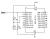
That circuit has been on the table for the past few posts. ref post #17

Like the rest of us, I am waiting to hear from 'aljamri' what is the problem really is.??

If he has followed the advice in the posts, he should have +1V on -Vref , +5V on +Vref.

A 250R resistor from ADC0 to 0V, with the 4mA thru 20mA from the signal current loop, this will give +1V thru +5V at the input of the ADC0 pin.
The PIC program has ADCON0 set up correctly, for the Vrefs etc..... so it should work.

So, 1V at the ADC0 pin gives 0 adc counts, for 5V at the pin gives 1023 adc counts.

Its method is not rocket science, its in common usage.

So aljamri what is the problem you are seeing.???:)
 
Last edited:
Hi ericgibbs this is my point aljamri using MiKro C he using the built in library he can set ADCON0 = any thing he wants and it's not going work


MiKroC mask off the ADCON0 bit as a matter of fact Adc_Read(2) will change it to a preset value to use RA2 the rest stay default
 
hi burt,
I dont use MikroC, so will take your word for that.

I hope he realises that ADC0 is not available.??
 
Sorry Sirs,

During my experiments, all of a sudden, my circuit stopped working except for 00.00 indications. Since then, I was trying to get it work to try all your valuable suggestions, but until today, No progress.

I'll check all my hardware, hoping that I did not made any harm to my only PIC16F876A .

Thanks For All.
 
He will have to wire his own code to read the ADC. If aljamri want I'll post him something that should work.
 
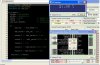
As long as my circuit refuses to operate, I turned my attention for the software trying to achive the zero shift and I think I've made some progress, here is the code and the OshonSoft shot is attached:

Code:
 char *value = "00.00 %";
 unsigned int ADC_Value;
 unsigned int adc_val ;
void main() {
  ADCON0 = 0b11000000;
  ADCON1 = 0b10001111;
  TRISA  = 0xFF;              // PORTA is input
  TRISB  = 0;                 // PORTB is output
  Lcd_Init(&PORTB);           // Initialize LCD
  do {
       adc_val   = ADC_Read(0);
 
       adc_value = adc_val - 204 ;          // To shift the 0 1V
 
       value[0] =  adc_value/82 + 48;      // (1024 - 204)/10 = 82
       value[1] =  (adc_value/8)%10 + 48;  // (1024 - 204)/100 = 8.2
 
       value[2] = '.';
       value[3] = (adc_value/1)%10 + 48;    // (1024 - 204)/1000 = 0.82
       value[4] = adc_value%10 + 48;
   Lcd_Out(1,5,value);
   Delay_ms(2000);
  } while(1);
       }

EDIT: I have to tell you that Nigle in post#13 here, and Eric in another thread, told me to do software-zero-shift. Thanks for both.
 

Attachments

  • OS7.JPG
    OS7.JPG
    104.3 KB · Views: 124
Last edited:
Status
Not open for further replies.

Latest threads

Back
Top