Continue to Site

Welcome to our site!

Electro Tech is an online community (with over 170,000 members) who enjoy talking about and building electronic circuits, projects and gadgets. To participate you need to register. Registration is free. Click here to register now.

  • Welcome to our site! Electro Tech is an online community (with over 170,000 members) who enjoy talking about and building electronic circuits, projects and gadgets. To participate you need to register. Registration is free. Click here to register now.

seven segment output problem

Status
Not open for further replies.
I did seven segment interfacing o simulation and on developing kit of 8051 and i was successful( when i did connect the seven segment only to the MCU in Proteus )
but now when i did implement it on my own general purpose PCB board with the circuit that is required for the hardware then i am getting error in output..

with the same circuit proteus also giving error on output

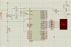
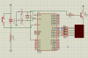
the circuit i am following is in the attached images

my code is as follows

C:
#include<reg51.h>
sbit a=P1^0;
int ar[]= {0x40,0xF9,0x24,0x30,0x19,0x12,0x02,0xF8,0x00,0x10};      // common anode segment
unsigned int i,j;
void main()
   {


   for(i=0;i<10;i++)
      {
      a=1;  //to the common pin of segment
      P2=ar[i]; // WHATS THIS POINTING TO....
      for(j=0;j<50000;j++);    // just for some delay

      }
}
 

Attachments

  • segment.PNG
    segment.PNG
    40.4 KB · Views: 368
Last edited:
I have placed in code tags.... Also.... I have placed a remark on a specific line..

You may want to swap the transistor for a PNP type...

no effect after using PNP type
can u tell me the appropriate circuit for this application.. with all the component that are required for this


and you quoted a line in the program
its "ar" instead of ar
 
Is your actual LED display CA or CC?

The most common mistake I see people make is they use the wrong type. In your circuit you show, you'll need a CA type, and you turn on a particular segment of the display by turning off its corresponding pin. Pullup resistors would be a good idea too.
 
Bob Parihar , just to clarify: The simulation worked but the actual circuit you built didn't, correct?
 
simulatuion works if i use no registers and transistor(NPN) in between the ports and seven segments

but the circuit i built is not correct.. thus i want an appropriate circuit which must work

Before we can give you a circuit you need to answer my question--is your display CA or CC?
 
You are trying to drive the transistor with a 10K resister... Well... 5v / 10000 = 0.5uA... It might not be seen... If you replace the resistor for a 470 ohm you will see something on ISIS.... You are also inverting the output so if you replace the transistor with a PNP and drive the base LOW!!! then it will work....

I have checked you code and it works fine if P1.0 is held low...

i am using a common anode seven segment
if P1.0 is held low.. and using a PNP transistor insted of NPN.. then seven seg of common anode configuration might not work
if PNP can be used then... how the common pin of seven segment will get positive voltage(high)?
 
Last edited:
Before we can give you a circuit you need to answer my question--is your display CA or CC?


iam using a common anode seven segment display sir

actually my real purpose is to multiplex two seven segment and then use it for display.. but first i want to test that does my circuit is correct for one seven segment.. that is why i am trying.. once i succeed then i will do multiplexing
 
i am using a common anode seven segment
if P1.0 is held low.. and using a PNP transistor insted of NPN.. then seven seg of common anode configuration might not work
if PNP can be used then... how the common pin of seven segment will get positive voltage(high)?
Your code implies that P1.0 is high.... If you want to drive the common anode you cannot use a NPN it must be a PNP,,, If you want to see anything you need to reduce the resistance value of the base resistor....

I have tried this and it does work.....
 
Your code implies that P1.0 is high.... If you want to drive the common anode you cannot use a NPN it must be a PNP,,, If you want to see anything you need to reduce the resistance value of the base resistor....

I have tried this and it does work.....

thanks to make me correct sir,

i did followed you by replacing PNP in place of NPN
now my circuit looks like this( in the attached pic)...
and i did make P1.0 low in the software code..
u can see it in picture
if this is correct.. why still iam getting a single segment on at all time...
 
Last edited:
I did sir!!!

Here's a snap shot of everything running in ISIS.... Notice the i variable at the bottom and the value in ar[7]..

View attachment 89365

Thanks for help

could two multiplexed seven segment could be run with the same circuit..
i mean both segment having separate transistors and the resistances of same value at there bases.
could it work or i have to take different value of base register
 
Yep!... However multiplexing comes with a new "pain in the a**" You need to separate the time between the displays..

The easiest way by far is to use a timer and an interrupt to share the time, needed to view both displays, accurately.

I have done a small C code version for the small pic16f628 in the articles section ( link in my signature ) The code needs porting over...

Then you need to update written values t the display in the main super loop.
 
Status
Not open for further replies.

Latest threads

New Articles From Microcontroller Tips

Back
Top