Continue to Site

Welcome to our site!

Electro Tech is an online community (with over 170,000 members) who enjoy talking about and building electronic circuits, projects and gadgets. To participate you need to register. Registration is free. Click here to register now.

  • Welcome to our site! Electro Tech is an online community (with over 170,000 members) who enjoy talking about and building electronic circuits, projects and gadgets. To participate you need to register. Registration is free. Click here to register now.

Seven segment circuit for scoreboard

Status
Not open for further replies.

sparky72

Member
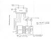
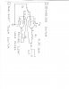
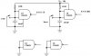
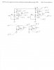
First of all let me say what I am trying to do. I want to build a digital scoreboard for playing horseshoes. I plan on using a 4543 latch decoder with a 4553 BCD counter & a manual pulse generator in conjunction with a momentary spdt switch which will count up 1 digit at a time per push. The home made seven digital display is approx. 5"x4", using 5 super bright leds in series for each segment of the seven digital display. The display will be powered by a 12 volt battery which will require a 125 ohm resister between the latch decoder and the a, b, c, etc connections on the display. Of course since the scoreboard will have to count up to 21, I will have to have 2 seven segment displays that will work from the momentary switch counting up from 1 to 21. This is where I get into a problem. I know the 4543 latch decoder will handle up to 3 seven segment displays, but I am not sure how to go about hooking 2 of them up. Since this is my first major project and I consider myself as a total greenhorn I would like to keep it as simple as possible. Any help or suggestions for a schematic or any other ideas for this project would be greatly appreciated. Thanks in advance for any help that I may receive.
 
The 4553 counter is 3 digit and uses multiplexing so there are 3 seperate digit drives from the counter. This means you connect the displays in a multiplex configuration. That is all the A segments together, all the B segments together etc. The use a individual digit driver the Digit 1 and Digit 2. The input to the digit drivers comes from the counter.
 
Seven segment display scoreboard

Thanks K7elp60 for the quick response. I do have a couple more questions for you just to get this clear in this old brain of mine. Do the connections from the BCD counter to the homemade LED display come from the DS1 & Ds2 terminals and if so, where do they connect to on the display. Are there any transistors or resistors in circuit from the counter to the display, and if so what would you suggest? Thanks again for your input as it has helped me a great deal.
 
The DS1 thru DS3 outputs of the counter are active low, so a normal configuration would be to use common anode displays and use a PNP transistor with the emitter to Vdd and the collector to the common anode terminal of the display. A resistor from the DS terminal of the counter to the base of the transistor. The Vdd of the displays has to be nearly the same as the counter Vdd. Another thing to consider is that the displays segment current needs to be 10mA or less for the 4543 driver. If the segments require more than 10mA then an external driver such as an ULN2004 can be used. It can drive up to as I remember 500mA.
Also you will have to add some sort of contact debounce for the input switch that you are using to initiate the count
 
Last edited:
Concerning the horseshoe diplay

Hello,
I am trying to do the same thing and was wondering if you put this circuit in the proteus simulator?

If so, can you please post it.

If not, can you please create it and post it or mail it to me at:

true_kingspud@yahoo.com

Thanks

I'm a greenhorn also and I can't seem to figure out your comments enough to make the circuit.
 
seven segment display scoreboard

Hi K7elp60
I have attached a schematic that we were relating to earlier that I found on the website for the MC 14553B data sheet. I hope that it is good enough for you to be able to view it. According to the data sheet for the MC 4553B the output current pin will handle 20ma. The 5 leds that I am using for each of the a, b, c, etc. segments, are in series using a 125 ohm resister rate at about 17 ma. per segment @ 12 volts VDD. The outputs from the DS1 & DS2 go through a resistor to a transistor base. The collector goes to the common cathode and the emitter goes to VDD. What resistance would you use @ DS1 & DS2 and what would you suggest to use for the transistors. Thanks again, I really appreciate your help.
 

Attachments

  • IMG_0004.JPG
    IMG_0004.JPG
    447 KB · Views: 2,376
I think the circuit uses common anode displays. The 4543 which drives the segements will only supply 10mA per segment, so you need to either increase the value of the resistor inseries with each segment or use an additional driver for the added current. The transistors for the DS1 and DS2 can be a pnp such as a 2N2907. I would use a 10K ohm resistor from the base to the DS pin of the 4553.
 
Seven segment scoreboard.

k7elp60 said:
I think the circuit uses common anode displays. The 4543 which drives the segements will only supply 10mA per segment, so you need to either increase the value of the resistor inseries with each segment or use an additional driver for the added current. The transistors for the DS1 and DS2 can be a pnp such as a 2N2907. I would use a 10K ohm resistor from the base to the DS pin of the 4553.

Thanks K7elp60, as usual you have been a big help. More questions though. It seems as though I have 2 choices now. I can either up the resistance to around 350 ohms to keep the output to 10 ma's to the display or use the ULN2004A driver chip. Since I would like to have the led display as bright as possible I am leaning towards the later. I assume that the ULN2004A connects the 1,2,3,4 etc. input pins to the a,b,c, etc.output pins on the MC14543B and the output pins of the ULN2004A go to the display. If my assumption is correct does it matter which side of the ULM2004A the resistors go on? Please feel free to correct me if my assumption is wrong. Thanks,
 
The inputs to the ULN2004 go directly to the output segments of the 4543. The resistors go between the ULN2004 and the Display segments. Make sure the PH pin(6) of the 4543 is logic 1. This makes sure the outputs are high to drive the ULN2004 properly.
 
seven segment display

k7elp60 said:
The inputs to the ULN2004 go directly to the output segments of the 4543. The resistors go between the ULN2004 and the Display segments. Make sure the PH pin(6) of the 4543 is logic 1. This makes sure the outputs are high to drive the ULN2004 properly.

Ok, now that I have the controller and driver latch circuits fixed in my mind thanks to your help, I would like to know if I am on the right track regarding the manual pulse generator. I have attached a bounceless switch for generating the pulse that I would like you to have a look at. If I use a spdt momentary normally off switch for s1 would this circuit do the job. The outlet pulse would go to the clk pin on the 14553. Looking forward to hearing from you again. Sorry for being such a pain in the butt with all my questions and I do appreciate your patience with me. Take Care
 

Attachments

  • IMG.jpg
    IMG.jpg
    389.9 KB · Views: 899
This circuit will probably work better. Both sections of the 4093 use momentary no switches. On power up the one that feeds the master reset has a longer time constant so the counter is reset to 0. The part of the 4093 that feeds the clock input to the 4553 also generates a clock pluse, but it's time constant is shorter so the pulse is ignored by the reset pulse of the reset generator. Pushing the reset button will also reset the counter when ever you want to.
 

Attachments

  • contact debounce.JPG
    contact debounce.JPG
    16.3 KB · Views: 563
k7elp60 said:
This circuit will probably work better. Both sections of the 4093 use momentary no switches. On power up the one that feeds the master reset has a longer time constant so the counter is reset to 0. The part of the 4093 that feeds the clock input to the 4553 also generates a clock pluse, but it's time constant is shorter so the pulse is ignored by the reset pulse of the reset generator. Pushing the reset button will also reset the counter when ever you want to.

Good stuff k7elp60; Would you mind giving me confirmation as to the pin #'s from the 4093 chip. I think that I have it right. I have attached a marked up version of the schematic that you sent to me for you to have a look at. Could you also tell me what the 1/4 inside the symbol means? Thanks again.
 

Attachments

  • IMG.jpg
    IMG.jpg
    309.4 KB · Views: 544
You have the pin connection correct for the 4093. Sorry about the confusion with the 1/4 marking. It just means each nand gate is 1/4 of the total package of the 4093.
I am glad to help out. As you probably know there are many ways to solve a problem with electronic circuits. In this case we seem to think somewhat alike. I have worked with both the 14553,4543,4093 and a number of other CMOS digital IC's.
Ned
 
k7elp60 said:
You have the pin connection correct for the 4093. Sorry about the confusion with the 1/4 marking. It just means each nand gate is 1/4 of the total package of the 4093.
I am glad to help out. As you probably know there are many ways to solve a problem with electronic circuits. In this case we seem to think somewhat alike. I have worked with both the 14553,4543,4093 and a number of other CMOS digital IC's.
Ned

Thanks Ned; I need all the help I can get as you probably know by now. This is all so new to me. So here goes again. As I was double checking the components I will be needing, to put my order in to Digikey, I realized that the resistance @ the a,b, c, etc for the led segments would have to handle 10 leds minimum, since both displays will be lit when the display unit is turned on. I plan on using super bright red leds that are rated @ if 30 ma.max & 1.9 v. I plan on using a 10 ohm resistor. Do you think this would be a good choice? As always, looking forward to your input. Lorne
 
Lorne, The individual digits will appear to be lit at the same time, but they won't be because of multiplexing. Pins 3 and 4 of the 4553 counter needs a capacitor(1nF). This sets the multiplexing frequency. I never try to run LED's at the maximum current. Your initial resistance of 125 ohms should be okey as the human eye will not see the flicker because of multiplexing.
Keep in mind that the maximum current for the LED's is generally for continious use. If they are being pulsed or in this case multiplexed and they are not bright enough then I would reduce the current limit resistors, but never exceed the maximum current on an average basis.
 
seven segment led display

k7elp60 said:
Lorne, The individual digits will appear to be lit at the same time, but they won't be because of multiplexing. Pins 3 and 4 of the 4553 counter needs a capacitor(1nF). This sets the multiplexing frequency. I never try to run LED's at the maximum current. Your initial resistance of 125 ohms should be okey as the human eye will not see the flicker because of multiplexing.
Keep in mind that the maximum current for the LED's is generally for continious use. If they are being pulsed or in this case multiplexed and they are not bright enough then I would reduce the current limit resistors, but never exceed the maximum current on an average basis.

Ok Ned; So what you are telling me is that, let's say for instance that we are talking about the"a" connection on the MC14543. First of all both "a" segments for each digital display are connected together so when power is called for, all 5 leds for each a segment they light up but they are actually pulsing so none of them are lit at the same time. It happens fast enough that they appear to be on at the same time. Ok, sounds good to me. I will let you know how I make out. I will be ordering my material tomorrow. Lorne
 
seven segment scoreboard

Good morning Ned; The more I look at the schematic for this project of mine the more questions I seem to come up with. Does the MC 14553B have the #8 pin connected to ground as well as the # 11 pin ? Does the # 16 pin connect to vdd or is the power supplied by the clock & reset input? Also regarding the MC14543B does the # 16 pin connect to vdd as well as the # 6 & #1 pin, does ground connect to # 8 pin as well as # 7 pin. The schematic does not show connections to the #8 & # 16 pins for either of these chips but the data sheet does. I assume that because the schematic does not show these connected there are none, but I just had to be sure. Thanks again for any input that you give me. Lorne
 
sparky72 said:
Good morning Ned; The more I look at the schematic for this project of mine the more questions I seem to come up with. Does the MC 14553B have the #8 pin connected to ground as well as the # 11 pin ? Does the # 16 pin connect to vdd or is the power supplied by the clock & reset input? Also regarding the MC14543B does the # 16 pin connect to vdd as well as the # 6 & #1 pin, does ground connect to # 8 pin as well as # 7 pin. The schematic does not show connections to the #8 & # 16 pins for either of these chips but the data sheet does. I assume that because the schematic does not show these connected there are none, but I just had to be sure. Thanks again for any input that you give me. Lorne
Lorne,
on the 14553 pins 8 & 11 to ground, pin 16 to Vdd, you also need to connect pin 10 (LE) to ground.
on the 4543 pin 16 to Vdd, pin 1 also to Vdd and pins 6,7,8 gnd.
Ned
 
seven sgment digital scoreboard

k7elp60 said:
Lorne,
on the 14553 pins 8 & 11 to ground, pin 16 to Vdd, you also need to connect pin 10 (LE) to ground.
on the 4543 pin 16 to Vdd, pin 1 also to Vdd and pins 6,7,8 gnd.
Ned

Good morning Ned. I received my components yesterday so things are starting to come together nicely. I am presently in the process of building the scoreboard itself. However I have another question for you if you don't mind. You mentioned that the # 6 pin of the 14543 goes to ground but according to the schematic for the display circuit, the # 6 pin is connected to the # 1 pin which goes to vdd. Should I disregard the schematic and connect the # 6 pin to ground? Thanks again. Lorne
 
sparky72 said:
Good morning Ned. I received my components yesterday so things are starting to come together nicely. I am presently in the process of building the scoreboard itself. However I have another question for you if you don't mind. You mentioned that the # 6 pin of the 14543 goes to ground but according to the schematic for the display circuit, the # 6 pin is connected to the # 1 pin which goes to vdd. Should I disregard the schematic and connect the # 6 pin to ground? Thanks again. Lorne
Lorne,
Pin #6 determines the output logic of the 14543, since you are using the ULN2004's they require a high output for drive, so pin 6 to ground insures this.
Ned
 
Status
Not open for further replies.

New Articles From Microcontroller Tips

Back
Top