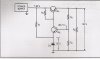
In the circuit shown , a technician measures the output voltage of the power supply at 30 V. Which is the correct statements ?
1) A collector-to-emitter short is present in Q1.
2) Resistor R2 is shorted.
3) Resistor R4 is open.
4) Resistor R1 is open.
I am choosing answer no. 2 in this case. Not sure though if i am correct. Because if R2 is shorted there is no voltage drop that will limit the base bias voltage at Q1.
When a load is applied to the power supply in the circuit , the output voltage tends to decrease. What tends to counteracts this action?
1) The conduction of Q2 decreases.
2) The conduction of Q1 decreases.
3) The voltage at the emitter of Q2 increases.
4) The voltage at the junction of R3 and R4 increases.
I am choosing answer no. 2 in this case, because the output voltage depends on the conduction of Q1.
Please help me to understand this circuit. Are my answers correct ?
")