Continue to Site

Welcome to our site!

Electro Tech is an online community (with over 170,000 members) who enjoy talking about and building electronic circuits, projects and gadgets. To participate you need to register. Registration is free. Click here to register now.

  • Welcome to our site! Electro Tech is an online community (with over 170,000 members) who enjoy talking about and building electronic circuits, projects and gadgets. To participate you need to register. Registration is free. Click here to register now.

series connection of battery cells with FETS

Status
Not open for further replies.
Kchriste: Thanx for the sketch. I understand that, the proposed circuit could be used for both cell charge and discharge. You wrote 'one between each cell' Do you mean, the 'OUT' of one cell connected to the 'IN' of the other?
If OUT = (-) and In = (+), or vice versa, then yes. ;)

I want to be able to connect just 1 cell, 2 , 3 etc in series when I decide to.
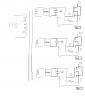
Do you want to be able to get multiple voltages from your cells? If so, there are better ways of doing this. What is the actual application that this will be used in? ie: Draw a schematic of the circuit that this will power. Show the FETs between the cells as switches for simplicity. There is probably a simpler way of doing what you want.
 
Last edited:
If I solder them together, I would not be able to disconnect the individual cells (electronically) when I want to.

put them in sockets

I want to be able to connect just 1 cell, 2 , 3 etc in series when I decide to.

Does anyone know how to realize this without using switches between them?

Thank you

no, this is what switches are for. If you put the FETs in series with the batteries, if you open one, they all open, so you are not switching one two or three battries into (again we ask) WHAT????? If you won't tell us your application, then everyone is just shooting in the dark trying to help you. We aren't trying to be difficult, but you are making it difficult for us to help you. If you are trying to power a circuit or load with 1.5, 3, or 4.5V, you are going about it the wrong way.
 
put them in sockets


no, this is what switches are for. If you put the FETs in series with the batteries, if you open one, they all open, so you are not switching one two or three battries into (again we ask) WHAT????? If you won't tell us your application, then everyone is just shooting in the dark trying to help you. We aren't trying to be difficult, but you are making it difficult for us to help you. If you are trying to power a circuit or load with 1.5, 3, or 4.5V, you are going about it the wrong way.

Thanks, Mike; because that is exactly what I and other have attempted to explain to the original poster. Without success......
 
Gentlemen/Gentle Ladies

I thought I explained the reasoning behind the series connection of the Mosfets: I will like to connect 2 cells ( to achieve say 4V), 3 cells (6V) etc to drive some load. However, I do not want to solder the cells together. I want to be able to electronically connect and disconnect them.

Mike: I believe it will be more useful to understand the specification of what I want to realize (which I have explained) and suggest a solution based on that specification. you posted a circuit sketch. This might be useful but some parts of the sketch can not be read. Can you, please re-post the same diagram?
Thank you.

Regards.
 
if I decide to connect just 2 cells , for example, I can bypass the 3rd 4th cell etc by connecting the 2nd cell to ground. The last cell will always be connected to ground. Once again, the issue is: HOW TO CONNECT MOSFETS IN SERIES.

Thank you.
 
I thought I explained the reasoning behind the series connection of the Mosfets: I will like to connect 2 cells ( to achieve say 4V), 3 cells (6V) etc to drive some load. However, I do not want to solder the cells together. I want to be able to electronically connect and disconnect them.
Then it would make more sense to connect all the cells in series and follow them with an adjustable buck switching regulator. That way, all cells will get discharged evenly. Your method could result in some cells becoming fully discharged while others remain fully charged. If these cells are then all used in series, the discharged ones will get reverse charged and be damaged.
 
Last edited:
Using your second drawing in post #6, you will need to keep your drivers completely isolated from each other, assuming you have to have what you drew up. Something like an isolation transformer with multiple secondaries to supply isolated power to driver. Then I can see it working ad drawn.
Kinarfi
edit, with the proper polarities observed, something like this may work, no secondary grounding.
 

Attachments

  • untitled..PNG
    untitled..PNG
    29.8 KB · Views: 148
Last edited:
Another thought, if you had 3 cells and 3 Fets feeding a 6 volt lamp, and you want to reduce the voltage to the lamp, as soon as you drop any one cell, the lamp goes out because they are in series.
You would need all the cells actually in contact with each other and then take the power from between 1 and 2 or between 2 and 3 etc. and turn off one fet before turning on the next fet and have the out put of each fet tied together and to the lamp.
Clear as Mud? have you ever tried to look through mud? it not clear!
kinarfi
 
I thought I explained the reasoning behind the series connection of the Mosfets: I will like to connect 2 cells ( to achieve say 4V), 3 cells (6V) etc to drive some load. However, I do not want to solder the cells together. I want to be able to electronically connect and disconnect them.

We've told you before, that will not work, as soon as you open one switch, the circuit will disconnected.

You could use P-channel MOSFETs and Schottky diodes but there will be a considerable voltage loss.

The best way is to use a an adjustable switching regulator as described above. That way, the batteries will all discharge at the same rate and you'll have a higher Ah capacity at the lower voltage settings.
 
I've not seen the entire post, but seeing that the OP want to connect the FETs in series I'll add an addendum:

With power fets (read: with the body connected internally to the source), always keep the source at the common (GND/-V in case of N-FET or Vsupply in case of P-FET). Othewise you are going to have the FET Body-Effect-> Reduced gain due the body connected to a floating voltage or a voltage different than 0V.
 
Status
Not open for further replies.

New Articles From Microcontroller Tips

Back
Top