Hi,
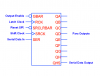
Thanks for the details, I got that diagram in micro cap. By the way, what is the latch and shift clocks? and also what is the purpose to use them? Can I fit in both with the same clock pulse? So in order to keep the circuit working, both GBAR and SRCLRBAR must be remained as logic "1" ? If I intend to make a 16 bits SIPO circuit, is that I need to fit QHS to the SER input in the next 74HC595?
Thanks

")