Continue to Site

Welcome to our site!

Electro Tech is an online community (with over 170,000 members) who enjoy talking about and building electronic circuits, projects and gadgets. To participate you need to register. Registration is free. Click here to register now.

  • Welcome to our site! Electro Tech is an online community (with over 170,000 members) who enjoy talking about and building electronic circuits, projects and gadgets. To participate you need to register. Registration is free. Click here to register now.

Serial in parallel out shift register

Status
Not open for further replies.

kpr123

New Member
Hello everyone,

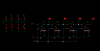
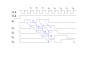
I am trying to design a serial-in parallel-out shift register for my 4-bit DAC. I tried simulating the following circuit but only the first few bits(serial in:01011)are shifting and the rest bits are disappearing. Am I missing something here?
Could someone please let me know what's wrong with it. It would be really helpful.
Thank you
 

Attachments

  • shift schematic.png
    shift schematic.png
    27.3 KB · Views: 189
  • shift out.png
    shift out.png
    44.8 KB · Views: 191
Are you asking why a four bit shift register only holds four bits?

Mike.
 
No.
I was expecting something like this(attachment) in the output. Shifting of the input bits
 

Attachments

  • 1.png
    1.png
    12 KB · Views: 193
serial input data given here is 01011, But the output that's getting shifted is different than the input.
 
It looks like there's something wrong with the first flipflop as d3 is wrong. Once d3 changes the change ripples through as it should. Double check the first flipflop.

Mike.
 
I take it that this is a simulator of some kind rather than real hardware.

The problem could be due to the relative timing of the clock pulses and the input data.

I suggest that you make the clock pulses narrower, say half the width that they are now, and, delay them slightly so that the clock edges do not correspond exactly with the data edges.

JimB
 
Thank you@JimB. I tried what you said but the result is the same. kindly go through the image
 

Attachments

  • shitout1.png
    shitout1.png
    79.1 KB · Views: 173
Mike I took the pos edged D flip flop with reset from the library itself. So I don't think there will be any problem with that.
 
No.
I was expecting something like this(attachment) in the output. Shifting of the input bits

I don’t know how accurate the DFF has been modeled, but they have a “setup time”. The D input has to be set BEFORE the rising edge of the clock.

eT
 
If the clock is inverted then the data will be stable when the clock goes high. If it doesn't work then something else is wrong.

Mike.
 
I have no time to do it myself but I would cheat checking the timing diagram of an IC doing that.

From the top of my head CD4094. Did lot of nice things with it.

Also 74LS595 maybe?
 
Status
Not open for further replies.

Latest threads

New Articles From Microcontroller Tips

Back
Top