I need some help in understanding an exercise.
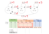
Here I have a State Diagram (Moore Machine), and the exercise asks me to write the table of transitions between states and machine outputs.
I can understand almost everything, but something is confusing me, the outputs expression, I have no idea how to determine what is the output value by those expressions. As I understand I have 2 Inputs A and B right? But I'm assuming that I can only have one value for my input like for example, in STATE S2 we can see (A⋅B') so for me That means (A )A=1 AND (B') B=0 so my OUTPUT Value should = 0 (1⋅0=0), in S1 we got A' that means my OUTPUT value should be 0, and so on... but I'm not shore if I am thinking correctly, if someone could explain me what I am doing wrong pls tell me.

* I hope I did design the table correctly, if I don't pls let me know, because other question is how can e represent the 3rd transition of S2 (A') with this table.
Normally in this type exercises the INPUTS are represented by 0's or 1's like this:

But as you can see in the exercise it is represented by expressions, while I don't realize it I can't determine the next state in the transition table.
Here I have a State Diagram (Moore Machine), and the exercise asks me to write the table of transitions between states and machine outputs.
I can understand almost everything, but something is confusing me, the outputs expression, I have no idea how to determine what is the output value by those expressions. As I understand I have 2 Inputs A and B right? But I'm assuming that I can only have one value for my input like for example, in STATE S2 we can see (A⋅B') so for me That means (A )A=1 AND (B') B=0 so my OUTPUT Value should = 0 (1⋅0=0), in S1 we got A' that means my OUTPUT value should be 0, and so on... but I'm not shore if I am thinking correctly, if someone could explain me what I am doing wrong pls tell me.
* I hope I did design the table correctly, if I don't pls let me know, because other question is how can e represent the 3rd transition of S2 (A') with this table.
Normally in this type exercises the INPUTS are represented by 0's or 1's like this:
But as you can see in the exercise it is represented by expressions, while I don't realize it I can't determine the next state in the transition table.