Continue to Site

Welcome to our site!

Electro Tech is an online community (with over 170,000 members) who enjoy talking about and building electronic circuits, projects and gadgets. To participate you need to register. Registration is free. Click here to register now.

  • Welcome to our site! Electro Tech is an online community (with over 170,000 members) who enjoy talking about and building electronic circuits, projects and gadgets. To participate you need to register. Registration is free. Click here to register now.

Sensing current through AC motor

Status
Not open for further replies.
That is what I have found for medium sized toroidal transformer. The number is larger for larger transformers.
I think, it will depend on the cross section area and the type of material (decide µe and saturation flux density) of the core. Right?

If the transformer is 0.25 V per turn (but it will vary depending on the design) then the 6 V winding will be 24 turns. So if the primary is 30 A and 1 turn, then the secondary will be 30 x 1 / 24 = 1.166 A
30/24 = 1.25 This is what confused me.
 
Hello, You could use a difference amplifier and a current transformer.

Try using one turn for the primary and a 20 turns for the secondary with a center tap connected to 5 vcc, the opamp 411 should be 12vcc and the feed back resistors 50kohm, The input resistors 500ohm should be ok and 1n4148 back to back diodes. As result you are going to have a 50% square wave if you have 30 amps you will have a higher voltage than when you have 10. Use thin wire 38awg or less for the secondary. Maybe the cores used as filter on monitor cables is ok for your application.


Good luck.
 

Attachments

  • wo92-9.jpg
    wo92-9.jpg
    31 KB · Views: 189
Your customer wants to know when the motor/pump is pumping water and when it isnt?
Why not just use a flow measuring device to tell you when the water is flowing A small turbine meter giving a pulse output will tell you.
....much easier than trying to measure ac current....
 
Your customer wants to know when the motor/pump is pumping water and when it isnt?
Why not just use a flow measuring device to tell you when the water is flowing A small turbine meter giving a pulse output will tell you.
....much easier than trying to measure ac current....
Is it to be fitted by cutting the water flowing pipe?
 
Is it to be fitted by cutting the water flowing pipe?


You could use an intrusive measuring device....Ultrasonic flow measurement is non-intrusive and could be clamped to the outside of the pipe....

All depends on what max flow rate you have and pipe size...
 
You could use an intrusive measuring device....Ultrasonic flow measurement is non-intrusive and could be clamped to the outside of the pipe....

All depends on what max flow rate you have and pipe size...
I think using current transformer may be cheaper solution than this for my purpose.
 
I bought a 50A/5A current transformer from shop. Can I convert it to DC by adding a bridge rectifier, filter and load? In this case to get 5V at 3A (my primary Imax is 30A), my load has to be around 5/3 = 1.67 Ω and power rating more than 15W. Is this correct?
Any other better method?
 
Check the transformer's VA rating (aparent power)

The transformer's output is 5 V @ 3 A, that gives 15VA. Some current transformers are rated at 10 VA.

You may use a lower value resistor to reduce the voltage at the output (ie with 2 V @ 3 A you have only 6 VA)
 
Check the transformer's VA rating (aparent power)

The transformer's output is 5 V @ 3 A, that gives 15VA. Some current transformers are rated at 10 VA.

You may use a lower value resistor to reduce the voltage at the output (ie with 2 V @ 3 A you have only 6 VA)

Thank you. Here the VA is written on the transformer as 5. That means for 3A secondary current(primary- 30A), I have to choose the load resistance in such a way as to maintain the secondary voltage less than 1.6V so that VA does not exceed 5 (here it is 0.55Ω). Am I right?
 
Thank you. Here the VA is written on the transformer as 5. That means for 3A secondary current(primary- 30A), I have to choose the load resistance in such a way as to maintain the secondary voltage less than 1.6V so that VA does not exceed 5 (here it is 0.55Ω). Am I right?

Yes, that's right
 
How about using that simple current transformer?

Make the primary winding with a wire for least voltage drop. Use insulated wire or stranded insulated wire for the secondary winding.

The primary winding is connected in series with the motor.

I suggest to use a transformer for each phase. If one phase is off the motor won't work, but burn up quickly. A 30A motor most is probably started directly (no star-triangle starting sequence)

That way you have dual control. Whenever the current drops with three phases at the motor the pump doesn't supply water. If one phase is off you know to shut down the motor immediately.

Boncuk
 

Attachments

  • current-transformer.gif
    current-transformer.gif
    87.1 KB · Views: 154
Last edited:
How about using that simple current transformer?

Make the primary winding with a wire for least voltage drop. Use insulated wire or stranded insulated wire for the secondary winding.

The primary winding is connected in series with the motor.

I suggest to use a transformer for each phase. If one phase is off the motor won't work, but burn up quickly. A 30A motor most is probably started directly (no star-triangle starting sequence)

That way you have dual control. Whenever the current drops with three phases at the motor the pump doesn't supply water. If one phase is off you know to shut down the motor immediately.

Boncuk
It would be good if I can get a current transformer which converts 30A to a few mA in the secondary so that I can use high resistance to get the required voltage and there won't be any power waste. But here 30A to a few mA may require higher turns ration (in the order of 1000) which is not practical manually with a toroidal core. Am I right? Any better suggestion to meet my requirement?
 
I don't know where your problem is. :confused:

No MCU understands current and expects voltage at the A/D converter.

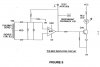
Here is an amplifier circuit with a total amplification of up to 1,104:1.

100µV voltage drop at the primary winding will give you enough voltage at the amplifier output to evaluate the motor condition. Using a toroidal core of 20 to 40 windings requires just 2 to 4 on the secondary side.

Also, I guess it's not a biggy putting a few windings of wire into a toroidal core, where you don't have to observe not to twist the wire to avoid breaking of the enamel. (Use 0.75 square mm household stranded cable for the secondary winding)

Please note the circuit is made to amplify negative voltage. Turn around the rectifier diodes to gain positive voltage.

If the output voltage is too low increase R4 value. R7 just reduces high spike charging pulses.

The time constant of R5, R6, R7 and C3 is 50ms.

The circuit is cheap to build and will do the required job properly.

Boncuk
 

Attachments

  • AMPLIFIER.gif
    AMPLIFIER.gif
    10 KB · Views: 146
Last edited:
My primary current is 30A max. Even with 1 turn in the primary my H=30AT. Toroidal core we choose should not get saturated at corresponding B. (B= µH)
With a turns ratio of say 20, my secondary current will be 30/20 = 1.5A.
Seems that you are suggesting to use a low resistance to generate small voltage which can be amplified for interfacing with my circuits. This will lower power waste.

For your comments please:)
 
Just forget about current.

The toroidal transformer will generate a small AC-voltage which just requires amplification and rectification.

100µV on the secondery side is sufficient to evaluate motor condition.

If you doubt an amplification ratio of 1,000:1 will lead to the desired result, use an instrumentation amplifier, such as an INA111 (Burr Brown) which can be programmed to any factor up to 10,000:1.

The coil on the photo I posted is used for household appliances such as TV-sets and works well with primary currents of max 2A.

Boncuk
 
With a turns ratio of say 20, my secondary current will be 30/20 = 1.5A

1.5A at a burden resistance of 500Ω results in a voltage of 750V. What do you want to do with them? :D
 
Just forget about current.

The toroidal transformer will generate a small AC-voltage which just requires amplification and rectification.

100µV on the secondery side is sufficient to evaluate motor condition.
In the case of current transformer, I have to anyway connect a load to take Ip/N current. Is it not?

If you doubt an amplification ratio of 1,000:1 will lead to the desired result, use an instrumentation amplifier, such as an INA111 (Burr Brown) which can be programmed to any factor up to 10,000:1.

Seems to be a expensive solution than using a current transformer with 30A primary rating and a higher turns ratio. Right?


Boncuk[/QUOTE]
 
With the toroidal transformer you suggested, what would be the secondary voltage if we connect 500Ω in the secondary? Take the primary current and turns ratio as you mentioned.
 
Status
Not open for further replies.

Latest threads

New Articles From Microcontroller Tips

Back
Top