Hello to all of you.
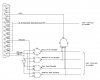
In a project which I'm doing for a company, I have been provided a ProSLIC 3210 evaluation board. Basically, the board takes in analog signals from a regular telephone and converts them to digital PCM signals.
We want to send the PCM signal into the PC. The problem is that the signals are sent in serial from the board; unfortunately, the board does not support the RS232 protocol. This leads to the idea of using the parallel port where we use a SIPO (serial-in-parallel-out) chip to send data into the computer. Here comes the questions:
1) Is it possible to program the parallel port in such a way that it receives and transmits 8-bits data on each way?
2) I plan to direct the incoming PCM data into the sound card to use its D/A converter so while speaking into the phone I can hear my voice out of the computer's loudspeakers. Is this redirection possible?
Lastly, are there any other forums that are similar to this one?
Thanks.")
In a project which I'm doing for a company, I have been provided a ProSLIC 3210 evaluation board. Basically, the board takes in analog signals from a regular telephone and converts them to digital PCM signals.
We want to send the PCM signal into the PC. The problem is that the signals are sent in serial from the board; unfortunately, the board does not support the RS232 protocol. This leads to the idea of using the parallel port where we use a SIPO (serial-in-parallel-out) chip to send data into the computer. Here comes the questions:
1) Is it possible to program the parallel port in such a way that it receives and transmits 8-bits data on each way?
2) I plan to direct the incoming PCM data into the sound card to use its D/A converter so while speaking into the phone I can hear my voice out of the computer's loudspeakers. Is this redirection possible?
Lastly, are there any other forums that are similar to this one?
Thanks.