Continue to Site

Welcome to our site!

Electro Tech is an online community (with over 170,000 members) who enjoy talking about and building electronic circuits, projects and gadgets. To participate you need to register. Registration is free. Click here to register now.

  • Welcome to our site! Electro Tech is an online community (with over 170,000 members) who enjoy talking about and building electronic circuits, projects and gadgets. To participate you need to register. Registration is free. Click here to register now.

Semester Final Build a adder, subtractor, mutiplier......

Status
Not open for further replies.

Juglenaut

New Member
Well my quest on this project is to accept the inputs from the 3-bit Adder, subtractor, mutiplier (doubler), half-divider and output the results in a 2 digit seven segment display.

This is a group me and a partner.

My partner took the easy way and did the compute part which come easy to me.

This is the assignment:

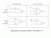
Input 2, 3-bit binary numbers, add these two numbers, provide means for dividing or doubling the result doesn't have to display resultant just have to show the instructor. Decimal remainders discarded. Display the result in 4-bit binary and 2 digit decimal form (7-segment only no LCD).

Any input would be appreciated, as you can see I am a newbie and you may bash me accordingly as I know this project is simple in its nature.

We can only use Simple IC's (no Micro procs), our kits are limited to LS series and some HC series IC's.
 
See if your library has the book:-
Pulse, Digital and Switching Waveforms by Millman and Taub.
See section 9-12 Binary addition. It also covers subtraction.

To multiply a binary number by 2 you simply shift it one place to the left(ie. add a zero to the right hand end. This equivalent to multipling a decimal number by ten.

To divide by 2, shift it the other way and insert a binary point.

Len
 
If you're using 7-segment decoder-drivers, make sure the model matches up with your LED's input polarity. Nothing is worse than going through all that trouble, then scrambling at the last minute to add a bunch of inverters because you picked the wrong chip. Use a 74LS47 if you're using an active-low display, or a 74LS48 if you're going to need an active-high LED.
 
I only have to deal with the BCD 8421 Outputs from his build...Inputs into my build for display in a 2-bit 7-seg. So far I can get it to show 10 and upto binary 1111 as expected, but I need to some how shift it so I can read 1,2,3,4,5,6,7,8,9,10,11,12,13,14,15....The first digit has to recirculate some how so I can get it to read 1 on a binary 1011, 2 on a binary 1100, and so on. Would a demultiplexer work???then re-encode it ???

I could just build my own complete project and it would probabaly would work better.

Our instuctor is testing us on cooperation.

Basically I only need to decode BCD 8421 to show 1 through 15 on a 7-seg display.
Digit MSD,LSD 2 bit decimal. This is what I need the display to show. A full 8-bit binary count.
ML
X0
x1
x2
x3
x4
x5
x6
x7
x8
x9
10
11
12
13
14
15

Although it may be just as easy to build one the shows decimal upto 99.
 
Quote:

Pulse, Digital and Switching Waveforms by Millman and Taub.
See section 9-12 Binary addition. It also covers subtraction.
END

Thanks, I will order it the next time I go to Barnes and Nobles if they don't have it.
 
Your latest post is hard to understand. I assume you want to know how to display a 4 bit binary number on two 7 segment displays so that, for example, 0101 is shown as 05 (or perhaps just 5) and 1100 is displayed as 12.

To do this, you need to subtract 1010 (decimal 10) from the binary number if it is > 9. This will give you the units digit in BCD and the 1 for the tens digit is simply the output of the comparitor that detects whether the number is > 9 or not.

If the number is <10, then you subtract 0.

Len
 
You editied your post (the one I said was hard to understand) while I was typing mine. Your edit is much clearer and is as I expected. So my comments stand.

Len
 
Well yes...that is about right.

Our instructor only want me to display 1-15 from a 4-bit input.

I am known to edit on the fly:)
 
I am using a 74150 multiplexer for the 10s digit.

I only have to show a 1 for the ten's place.

I just need the 1's digit place to count:
0
1
2
3
4
5
6
8
9
0
-----I got this far??
1
2
3
4
5

Should I use a Parallel Load shift regs??Instead of a mutiplexer??
 
I have been thinking about this for over 2 days and failed 2 attempts.

My next try is:
Using a 74154 Demultiplexer 1 of 16
(2) 74147 decimal-to-Line BCD priority encoder
(3 or 2) 74194 4-bit bidirectional uni-shift regs
(2) BCD to 7-seg driver 7447
(2) hex inverters.

We don't have the 7448:(
I dunno arrrrrrr.
 
Juglenaut said:
I am using a 74150 multiplexer for the 10s digit.

I only have to show a 1 for the ten's place.

I just need the 1's digit place to count:
0
1
2
3
4
5
6
8
9
0
1
2
3
4
5

I assume you connect 0 to the 0 to 9 inputs of the 74150 and 1 to the rest. This seems a clumsy way to do it, but will work.

As an alternative to what I suggested earlier, I would be inclined to use a magnitude comparitor to determine whether the digit is >9 or not. If greater than 9, add 0110 (decimal 6) to the number and ignore the overflow. If <10, add 0000 to the number.

Len
 
The only compararator I have is a 74HC85.


On the 74150 I have the data select of all the inputs and the inputs either tie low or high to give a result of 10 or higher, and when it hits higher than binary nine the W not goes low and tigger 1 to apear on the 10's digit.
 
Juglenaut said:
On the 74150 I have the data select of all the inputs and the inputs either tie low or high to give a result of 10 or higher, and when it hits higher than binary nine the W not goes low and tigger 1 to apear on the 10's digit.

That's alright. You're using the 74150 as a comparitor.

Len
 
I just need to figure out how to accept the BCD 8421 input for the ones digit and when it hit 10 in binary it discards the 1 so that the diplay read correctly..

it has invalid diplays past 9 on the 0nes digit. That when I encoded it and the decoded it to get upto decimal 10.
 
I am very limited on resources and can only get certain chips if given permission only because it would make it easy and since this is a final I can't get chips the resource room is locked!!!!!!


I been looking for schematics even on 4 and a half digit drivers, but most all are block so I am very lost.

I could just get a schematic for a 4 digit LED display man I would have it made:)

I am tempted get an old calculator and use chip out of that.
 
The use of either a Multiplexer or a Comparitor is an over kill.

It can be done with a single NAND or NOR gate package as below.

The Boolean funcion is D.B + D.C = D.(B + C).

The option are drawn below.
 

Attachments

  • Gating_759.gif
    Gating_759.gif
    5.8 KB · Views: 521
Juglenaut said:
I just need to figure out how to accept the BCD 8421 input for the ones digit and when it hit 10 in binary it discards the 1 so that the diplay read correctly..

it has invalid diplays past 9 on the 0nes digit. That when I encoded it and the decoded it to get upto decimal 10.

I don't understand this post. I assume you wenat to convert binary into BCD so it can be displayed on two 7 segment displays. The simplest way I know of is to use an adder as I suggested in an earlier post.

If the number is > 9, add 6 to the binary number to obtain the correct units BCD digit.

Len
 
Juglenaut said:
I been looking for schematics even on 4 and a half digit drivers, but most all are block so I am very lost.

I could just get a schematic for a 4 digit LED display man I would have it made:)
I don't understand these points either.

What is a 4 and a half digit driver?

And what do you mean by a 4 digit LED display. I thought you only needed a 2 digit display.

A drawing is worth a thousand words.

Len
 
Thanks I am already on the way.

Sorry for the mass confusion.

I guess I was prodding for further details hehe.
 
I have drawn 2 options below. Is this what you want?

If so, which option do you prefer? The "gating" is simply combinational logic composed of NAND and/or NOR gates.

Do you know about Karnaugh maps?

Len
 

Attachments

  • 7_segment_logic.gif
    7_segment_logic.gif
    7.3 KB · Views: 621
Status
Not open for further replies.

Latest threads

New Articles From Microcontroller Tips

Back
Top