Continue to Site

Welcome to our site!

Electro Tech is an online community (with over 170,000 members) who enjoy talking about and building electronic circuits, projects and gadgets. To participate you need to register. Registration is free. Click here to register now.

  • Welcome to our site! Electro Tech is an online community (with over 170,000 members) who enjoy talking about and building electronic circuits, projects and gadgets. To participate you need to register. Registration is free. Click here to register now.

SCUBA Torch Circuit; why no 'off' in the toggle sequence?

Status
Not open for further replies.

Klemheist

New Member
Hi Guys,

This circuit was kindly suggested to me by another blogger for a SCUBA torch I am building.

It will have two 12watt LED heads with one momentary piezo switch. I need a simple circuit that can toggle through using one momentary switch, so that the torch can have one LED on, both on and an OFF position.

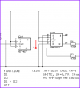
This circuit with a 4027 dual flip flop and a couple of FETs acting as relays is supposed to give this sequence;

A on
B on
Both A & B on
Both OFF

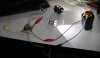
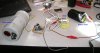
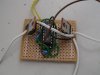
In the test bed it toggles through the first three only, with no OFF in the sequence.

Can anyone please help?

(The circuit is attached and a photo of the test bed).

Cheers

Klem
 

Attachments

  • DUO-TOGGLE-SWITCH-SCH.pdf
    36 KB · Views: 334
  • test bed 1.jpg
    test bed 1.jpg
    34.1 KB · Views: 397
hi Klem,
The original circuit should work correctly.

At power ON, C3 creates a positive clock pulse which Sets Q1a, this going high clocks Q2a high, so both LED's are off.

1st clock, resets Q1, so D1 is on.

2nd clock Q1 is set , so D1 goes OFF, as Q1 goes high it sets Q2 off, so D2 goes ON.

3rd clock resets Q1, so D1 goes ON also D2 is still ON.

4th clock sets Q1, so D1 goes OFF, as Q1 is set high, so it sets Q2 high, so both D1 and D2 are OFF.
 

Attachments

  • AAesp06.gif
    AAesp06.gif
    30.8 KB · Views: 211
Last edited:
Hi Klem,

hopefully you remember who posted that circuit. :)

Please check the logic states of the four attached screenshots. (red=H, blue=L)

The circuit does also work switching all LEDs off.
 

Attachments

  • OFF.gif
    OFF.gif
    9.7 KB · Views: 264
  • ONE-ON.gif
    ONE-ON.gif
    9.8 KB · Views: 316
  • TWO-ON.gif
    TWO-ON.gif
    9.7 KB · Views: 183
  • BOTH-ON.gif
    BOTH-ON.gif
    9.8 KB · Views: 188
This change will start with D2 led being ON.

Or possibly both LEDs being ON.

He would then need to tap the switch to turn them OFF, satisfy himself that the circuit is functioning properly and the battery is good.

Not a bad idea afterall. :D
 
Or possibly both LEDs being ON.

He would then need to tap the switch to turn them OFF, satisfy himself that the circuit is functioning properly and the battery is good.

Not a bad idea afterall. :D

'In theory' :),, the C3 to +V and the 100k to 0V will provide the initial clock pulse to set both 74's, so both LED's off.
 
HI Boncuk,

Of course I remember it was you...note I said "kindly provided."

With no technical replies my latest post in our earlier thread and I surmised you were absent or had left the site...hence the new thread to all.

Thanks everyone for replying

Klem
 
Granted the circuit is correct, in both initial design and my build, what could possibly be causing a toggle sequence with no OFF?

Could it be one (or both) of the LED modules that I have used, interfering somehow?

The voltage supply is a 2-cell Li-ion battery pack, so 8.2V when fully charged.

Regards

Klem
 
I would probably use an SMPs to power the LED to increase the battery life.
 
Last edited:
Granted the circuit is correct, in both initial design and my build, what could possibly be causing a toggle sequence with no OFF?

Could it be one (or both) of the LED modules that I have used, interfering somehow?

The voltage supply is a 2-cell Li-ion battery pack, so 8.2V when fully charged.

Regards

Klem

hi,
Do the following check, switch ON the power supply to the pcb, both LED's should be OFF.

What type of push switch for stepping thru are you using.?

Lets know.:)
 
Can you have a SMP supply in a hand-held torch? Is it really needed for this circuit to work?

I attach modular protection circuits to the Li-ion packs... for overvoltage, overcurrent and undervoltage protection, but unlikely they perform the same function as a SMP.

Cheers

Klem
 
Yes, I see your point...perhaps it is in the time the contacts are closed

In the test bed it's just two bare wires for the momentary switch. I have just been touching them together for less than a second of contact.

The intended switch is a piezo switch, which I gather is about 0.5 secs of contact per normal press of your finger.

Klem

hi,
Whats supposed to happen is that C3 1uF and 100K generate a clock pulse when the battery is connected, that puts the LED's in the OFF state.

The other pulses are manual from the switch, if its a noisy switch you will get multiple clocks at each press.
 
OK, have been playing with it (no pun intended!)

Can confirm both LED's come on when battery is first connected, every time.

Also, actually got an OFF one time when toggling through multiple times. Then another time the OFF happened for a split second, then it went onto the next in the sequence

It seems to be something to do with timing, switching timing maybe.

Photo of the settup right now. Note the two bared yellow wires I'm using to mimick a momentary switch

Klem
 

Attachments

  • test bed.jpg
    test bed.jpg
    46.1 KB · Views: 184
OK, have been playing with it (no pun intended!)

Can confirm both LED's come on when battery is first connected, every time.

Also, actually got an OFF one time when toggling through multiple times. Then another time the OFF happened for a split second, then it went onto the next in the sequence

It seems to be something to do with timing, switching timing maybe.

Photo of the settup right now. Note the two bared yellow wires I'm using to mimick a momentary switch

Klem

hi,
Bare wires as a switch is a no go.!, connect at least a n/o push switch.

Are you making the connection to the battery the same way, just touching the wires on.??
 
hi,
Looking a the pcb photo the 1uF wiring area looks wrong.??

Can you recheck it, the +end of the 1uf is to +6V and the 0v end to pin3 of the ic.?
 
OK I've attached the piezo...see photo. It's glued into the bottom half of the torch housing

Battery connection is via a Deans 80A plug in right of photo

Klem
 

Attachments

  • test bed update.jpg
    test bed update.jpg
    31.4 KB · Views: 159
Hi Klem,

the HCF4027 even reacts if you caugh heavily. :D

Please check the following items:

- wires to power LEDs of sufficient cross section (to prevent surge on the IC-power pin)

- is there an electrolytic cap connected directly between battery and circuit?

- is a 100nF bypass capacitor connected to the HCF4027 power supply pins?

- is the piezo switch bounce free?

If all of the above questions can be answered with "YES" then try this add-on circuit. It debounces the worst quality switch and provides a clean clock pulse of minimum 50ms width.

Clock pulse time = switch operating time + RC-time

Boncuk
 

Attachments

  • DEBOUNCE-01.gif
    DEBOUNCE-01.gif
    10.1 KB · Views: 175
Unsure whether the cables are rated for the power draw. I've used larger speaker cables for the FET's and LED's but normal thin hook-up wire for the circuit.

No electrolytic cap between power cables. I do not need the LEDs to be OFF when first connecting the power so I didn't source it, but if this component helps with noise then I will attach it.

The 100nF across the power pins is there, although the ground cable goes from battery to the FETs first before the circuit board (if this is important)

Unsure whether a piezo is bounce-free. Looking for this through the internet it appears it might be but I see nowhere where it is clear, including the manufacturer's website. The sequence iwthout OFF is the same without the switch (just touching switch wires together), so perhaps it is unrelated to the switch.
 
Status
Not open for further replies.

Latest threads

New Articles From Microcontroller Tips

Back
Top