Continue to Site

Welcome to our site!

Electro Tech is an online community (with over 170,000 members) who enjoy talking about and building electronic circuits, projects and gadgets. To participate you need to register. Registration is free. Click here to register now.

  • Welcome to our site! Electro Tech is an online community (with over 170,000 members) who enjoy talking about and building electronic circuits, projects and gadgets. To participate you need to register. Registration is free. Click here to register now.

SCR triggering

Status
Not open for further replies.

newfey

New Member
Hi,

I'm so happy to find this forum.
I have a question.

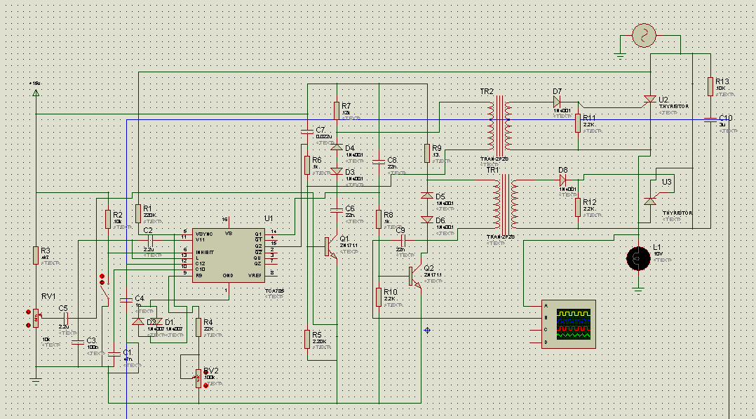
I have two SCRs in my circuit. I know how a/an SCR is triggered.
Both of them are off at first. Then when I trigger SCR1 , it will become ON.
And as it becomes ON, the capacitor starts to charge.
Then SCR1 is off and SCR2 becomes ON. And it continues ...

My question is this:

I want to trigger these SCRs with IC 555 and control them becoming on or off by their firing angle (with a potentiometer).
How should I change my circuit to gain this?

**broken link removed**

I'm grateful for your help.
Many Thanks ...
 
This is a simple Forced Commutation SCR setup. Once the First SCR is fired, it will be necessary to fire the Second to Shut Off the First and Vice Versa. The total shut down can take place Only by disconnecting the 12 V supply.
There cannot be any Firing "angle" adjustment in this setup.

If you are planning to construct a Invertor using these SCR's, you need to configure a "bridge" type using 4 SCR's where the ON time of the SCR's can be controlled to regulate the output AC.
Thanks a lot.
but I didn't get it. How could I make a bridge? They're not diodes. They have a gate too.
Could you give me an example circuit?
 
If you are attempting to design a forced commutation push pull inverter there are several errors:

RV1 should not be there
U2 is connected backwards
There is a missing inductor from the junction of the two cathodes to ground
You require isolated, alternating pulse generators to drive the gates
PWM control is not possible with forced commutations SCRs
C2's value is sky-high and should not be an electrolytic
Thanks a lot for helping
 
Hy newfey,

To be able to help with your project we would need more information:

(1) What is your objective. Are you making a 12V to 50Hz 240V RMS inverter or 60Hz 110V RMS inverter?
(2) What current capacity does the 12V supply have. Is it an automobile battery.
(3) What is the current load on the secondary of the transformer.
(4) What are the technical details of the transformer.
(5) How would you feel about using another switching element in place of the SCRs.
(6) By how much do you want to adjust the voltage on the secondary of the transformer?

spec
 
Last edited:
Thank you so much.


Thanks a lot for helping.


Thank you very much.

My Project is controlling AC power by varying phase angle (Firing angle or delay angle) of the thyristor.


As you said the first simulation I did was so primary and basic.
I started to read a lot about it.
Finally I decided to use this circuit:
28f8new.png

Does it seems so complex? I found it in TCA785 datasheet.
I f you google you will find the simulation videos on You tube.
If my Proteus simulation file is needed I'll upload it anywhere you prefer.

I have a problem here.
When I simulate it, it doesn't show me the output signal!

Does anybody have this circuit simulation?
It's very necessary for me./
 
Last edited:
Delete this post.
 
Last edited:
This is like a 50 year old design technology. Get the feeling you're doing somebody's homework.

Speaking as somebody who designed power converters for 25 years: you start with a design objective (Vin, Vout, load current, etc) and then select the best topology for what you need to do. You don't start with some dinosaur circuit and try to find simulations of it.
 
Just to support what Bounty says, that circuit could not be recommended: it is old, overly complex, and uses SCRs. In my experience SCR inverters are troublesome, much better to use MOSFETs or possibly Insulated Gate Bipolar Transistors (BJTs).

spec
 
Last edited:
It has been 45 years since I worked with SCRs. I remember you have to connect the trigger wire to 1 of the SCR power terminals then connect them to an AC transformer. When the AC transformer goes, plus, minus, plus, minus, plus, minus, plus, minus, SCR1 and ACR2 with go, on. off, on, off, on, off. They work like diodes connected like this. You can apply power to and SCR and no current flows until you apply power to the trigger wire. Once the SCR is ON it will not turn off until the power if off or the power goes from negative to positive. The only way to do what you want is use reversing relays to swap positive and negative back and forth to the SCRs then the 555 timer can be used to turn the relays ON/OFF at any duty cycle you want from 10% to 90%. One relay with DPDT contacts will work to reverse the DC to each SCR. When SCR1 is positive SCR2 has to be negative, relays switch then SCR1 is negative and SCR2 is positive. This was one of my learning projects in college electronic lap class. As far as electronic goes it was the stone age everything was just starting to switch from vacuum tubes to solid state.
 
No doubt that today you have power devices that can be turned ON AND OFF by a voltage on it's gate or similar terminal. But, it must be recalled that there were/are SCR invertors used commercially. I have handled a 35 KVA 240 VDC to 240V Invertors back in the 80's.
The technology of what the OP proposes is old, But workable.
 
No doubt that today you have power devices that can be turned ON AND OFF by a voltage on it's gate or similar terminal. But, it must be recalled that there were/are SCR invertors used commercially.
When I worked at Power Ten our prime competitor used SCR technology (around 1980) their name was EM which was Electronic Measurements Inc. We ate their lunch by going to HF switchers because the huge, heavy magnetics were reduced in size. We made the same power output switching converters that were half the size and 1/5 the weight. SCR designs were losers the minute high current bipolar and MOSFET transistors became cheap and available. EM stopped using SCRs and switched to transistor converters.
 
Thank you so much.


My Project is controlling AC power by varying phase angle (Firing angle or delay angle) of the thyristor.

28f8new.png


I have a problem here.
When I simulate it, it doesn't show me the output signal!

./

As I mentioned in the other forum, the diagram you drew here is FULL of errors.
 
Why 2 firing transformers, do you need to fire - and + part of the cycles at different times?
A single trans with 2 secondaries might be better.
With 2 trigger trans you'd have a hard time getting the triggering equal on - and + cycles, not a problem unless your load happens to be a transformer, which would get very upset with uneven triggering.
 
Status
Not open for further replies.

Latest threads

New Articles From Microcontroller Tips

Back
Top