MrDEB
Well-Known Member
in a quandry about which scr to use.
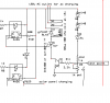
the attached schematic shows proposed circuit.
the 4n26 turns on the scr. when the opti turns off the scr/relay combo stays on until desired battery charge is achieved.
I know it isn't pretty but had to do lots of substituting so all the parts could be purchased from the electronics goldmine.
its a challenge. kinda reverse engineering.
here are links to proposed part data sheets
the holding current is whats throwing me fits but haven't done much with scrs. In this circuit I am switching dc not ac. the contacts are connected to an ac charger. the circuit opens the relay contacts when desired charge is achieved.
the 4n26 requires a max of 10 ma on the led thats why the 1k ohm resistor
data sheets
buying from The Electronic Goldmine
https://www.electro-tech-online.com/custompdfs/2009/10/2N6400-DPDF.pdf
MCR100-3 pdf, MCR100-3 description, MCR100-3 datasheets, MCR100-3 view ::: ALLDATASHEET :::
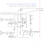