Continue to Site

Welcome to our site!

Electro Tech is an online community (with over 170,000 members) who enjoy talking about and building electronic circuits, projects and gadgets. To participate you need to register. Registration is free. Click here to register now.

  • Welcome to our site! Electro Tech is an online community (with over 170,000 members) who enjoy talking about and building electronic circuits, projects and gadgets. To participate you need to register. Registration is free. Click here to register now.

Schottky Voltage clamp

Status
Not open for further replies.

slosjo

New Member
Hello all-

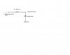
I need help understanding how a Schottky voltage clamping circuit works. Specifically, I have a 5V microcontroller that will be sending a serial stream to a 3.3V device.(the "1's" in the serial stream need to be at 3.3V when they arrive at the 3.3V device) From what I have read, a Schottky clamping circuit would be the best option because of the recovery speed of those diodes. I don't quite understand how these circuits work and haven't been able to find anything really great online explaining one. I have attached what I think the circuit should look like; any help would be greatly appreciated.

Thanks

slosjo
 

Attachments

  • schematic.JPG
    schematic.JPG
    36.9 KB · Views: 2,740
All diode-rail clamps work like this:

When the voltage on the line is too low (or high) to forward bias the diode, it's like the diodes aren't there. When the voltage gets high enough (or low enough) to forward bias the diode the diode turns on and current flows through it. The extra current makes the voltage source droop since it can't provide enough current to push the voltage beyond 3.3V+Vf.

If the source is too powerful and the current can supply more current than the the diode can handle before drooping enough to fall below the clamp voltage (to turn the diode off), you place a resistor in series so that it limits the current and the extra voltage (minus the voltage drop of the diode) is dropped across the resistance.

The clamp voltage is +V+Vd if the diode is connected to a positive rail or -V-Vd if the clamp voltage is connected to a negative rail. So whether you clamp the voltage's upper limit or lower limit depends on the rail that the diode's anode is connected to. So if you use two diodes and two separate rails you can clamp the line voltage to within Vd of those rails.

Vd=forward voltage drop of the diode
+V = 3.3V in your circuit

In your specific circuit the anode of the diode is 3.3V and the cathode is the line voltage. So you can see that once the line voltage exceeds 3.3V+Vd (the clamp voltage), the diode will turn on and current will drain through it. Below that voltage, the diode is closed and has no effect on the line voltage. If you replaced 3.3V with 0V, then the line voltage would be clamped to Vd, and if you replaced 3.3V with -3.3V, then the clamp voltage would be -3.3-Vd (can you see that if this is the case, the diode will start to conduct if the line voltage gets too low?).

It works almost like a controlled short-circuit.
 
Last edited:
Status
Not open for further replies.

Latest threads

Back
Top