Continue to Site

Welcome to our site!

Electro Tech is an online community (with over 170,000 members) who enjoy talking about and building electronic circuits, projects and gadgets. To participate you need to register. Registration is free. Click here to register now.

  • Welcome to our site! Electro Tech is an online community (with over 170,000 members) who enjoy talking about and building electronic circuits, projects and gadgets. To participate you need to register. Registration is free. Click here to register now.

Schematic Idiocy

For The Popcorn

Well-Known Member
Most Helpful Member
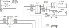
Am I allowed to hate whomever drew this schematic? In order to avoid crossing lines, the pins on pairs of connectors are shuffled. Pin 2 on one side connects to 2 on the other side....but they don't line up with each other. In this case, two pairs of connectors in line are shuffled.

This particular connector also has a problem where a 13 pin connector has a pin 14 in one place.

Sure, the schematic looks neat, but trying to follow signals from one end to the other is a mind-numbing experience!

20250309_191633.jpg
 
Without more of the schematic it is hard to say. But, in general . . .

A schematic is not a wiring diagram. I have around a dozen LM555 decals in my design library, and the only difference among them is the pinout. Same for a bunch of CD4060 decals. What is important in a schematic is a clear, unambiguous presentation of signal flow. A schematic shows the signal relationships between/among components. It is about communication, not geography. Another view is that a schematic tells the story of the designer's intent. Like a book, it has a beginning, a middle, and an ending, with paragraphs, sentences, nouns, verbs ... If all of the words on a printed page are in alphabetical order, the meaning of the writing is obfuscated.

Of course there are exceptions and tradeoffs depending on the circuit, the application, and the use of the schematic. Also, connectors often present unique challenges, causing a debate on whose clarity is more important. But in general, I'm with the "minimize crossovers / optimize signal flow paths" camp.

ak
 
I do agree that the schematic is… confusing.

A schematic is also a roadmap that will allow anyone unfamiliar with a circuit to follow and navigate the signals. As drawn, there is a discontinuity on the path, and although it can be followed, your eyes have to jump from the signal you are following and search where it goes to. Unnecessarily complicating the life of whoever is attempting to troubleshoot the circuit.

It would be nice to see a larger portion of the schematic, to see if there was a reason to draw it that way. My suspicion is that he wanted to have nice straight lines without cross over.
 
It probably does make some sense, but my first thought was that the colors in a wiring harness were different than the colors going into it (i.e., the red wire is connected to the blue wire.....). This arrangement makes it very difficult to highlight wires from start to end. The complete tidy-fits-on-a-page schematic is attached below.

[Early project reveal]

This schematic is for a rotating-tray cold food vending machine – the kind where you press buttons to rotate the sandwich you want to the window, and slide the window open to pull it out. Due to a huge ponzi scheme failure and a hasty auction, we had an opportunity to buy a number of these machines for an average of $12 each. Since covid and work-from-home, the market for a cold sandwich made in a factory two weeks ago has shrunk to near zero.

Our thought is to use these machines to sell parts of interest to makers. Kits of components, Chinese modules, STEM supplies, etc. and non-electronic stuff too. A makerspace might like one so people have access to things that either take weeks to get from China or are a crap shoot from Amazon or ebay. Profits would be shared with a makerspace or other location hosting a machine. Crazy? Probably. But the cost to find out will be low.

To bend the machine to our will and to provide updated features, we're updating the control board. My hope is/was to make use of this interface board. It have some features we won't use and lacks some we need, so the jury is out at the moment. One strange feature of this machine is using 30VDC on the door position microswitches and converting it down to 5VDC for the controller board.

The interface board is connected to the controller with a 16 pin ribbon cable. My initial thought was that this was parallel I/O, but adding up all the things to be monitored and controlled that idea falls apart. We pick up the machines this week – we haven't had any hands-on time yet. My current thinking is that the switches go into a mux chip and converted to binary. That would convert 10+ switch signals down to 4 bits.

Wish me luck please!

Screenshot_20250310_080607_Edge.jpg
 
I agree that it is a wiring diagram rather than a schematic, it is a sandwich machine wiring diagram.

As wiring diagrams go, it seems quite reasonable, no where near the worst that I had to deal with in my day job.

As for the wiring shuffle around J29A, I guess that the mass of micro switches (top right of drawing) was devised by the electro-mechanical guys who designed the machine.
The same guys may even have bought the control system, and as an afterthought told the computer guys "connect it up and make it work".
And this is why is looks like a bit of a dogs breakfast.

Have fun.

JimB
 
Very messy zig zag connections vs simple bus wire and no clue how to interface switches. NO position is unused on all SPDT switches.

1741629260670.png


1741629428118.png
 

Attachments

  • 1741627041845.png
    1741627041845.png
    169 KB · Views: 51
Last edited:
The switches need to arc if not gold plated (any switch rated for >=2A) to wet ( clean with an arc) oxide insulation that is inevitable. I found P&B relays failed with TTL in the 70's with extra contacts for feedback. I used a pullup and 22 uF Tant across contacts to fix that. Perhaps 30V and 1uH of wiring does the same.(?) unlikely...
 
Last edited:
One strange feature of this machine is using 30VDC on the door position microswitches and converting it down to 5VDC for the controller board.

Almost certainly "Wetting" voltage to guarantee operation with slightly tarnished contacts.
A lot of basic microswitches etc. act up after a while at 5V, then need more to guarantee conduction.
(And those switches are a lot cheaper than ones with appropriate alloy contacts for low voltage operation).
 
I had thought about that topic. I think the switches are standard Microswitches, so at least they can be readily replaced if need be.

The machine uses a strange combination of 24VAC, regulated 24VDC and non-regulated nominal 30VDC, along with 5VDC. I'm considering replacing the line transformer with DIN rail 24VDC and 5VDC supplies (depending on how things actually look).

Much fun ahead I'm sure.
 
Not much wetting current with 100 pF/m wiring on closure or logic load current on breaking contacts.
Marginal solution. Far better to use 5V with low ESR cap.
 
Tony Stewart, please describe the cap circuit. I'm not sure exactly what you mean.

Thanks.
 
1741637185213.png


If e-cap low ESR is 1 Ohm then you get 5A pk decaying to 37% of 5V in 100 ms when open.

Std e-cap ESR is 100x more than low ESR but depends on quality (Japanese/Korean/German vs others)

ESR* C= Tau is constant within same family of parts & voltage.
 
Last edited:
Thanks Tony. Got it.

I did realize this machine's switching arrangement isn't like a typical switch/pullup arrangement used with microcontrollers. The 30VDC supply to the switches isn't current-limited like a typical pullup arrangement - it's a stiff voltage source. I believe it feeds a voltage divider on the interface board from what I can see in pictures of the board. I don't know what the current through the switch is.

existing system.jpg


If I keep a similar system, I might do something like this. 24VDC to the switches, feeding a MC1489 quad line receiver (from the pre-MAX RS232 days). It will sink about 6mA from a 24VDC source when the switch is closed. Sufficient to clean contacts?

proposed system.jpg
 
Not much wetting current with 100 pF/m wiring on closure or logic load current on breaking contacts.
If the contact has tarnished to the point of not conducting without a higher voltage, how does a cap help with the low voltage? Surely such a high capacitor value will just cause the contacts to burn more when they are closing properly?

There are thousands (or millions) of industrial machines with switches connected directly to 24V PLC inputs that only put around 3 - 5mA load current through those switches, and they work fine for decades.
 
I can only verify my personal success when I was in Aerospace R&D in the 70's using P&B relays. I did this before SCADA and PLC were even an acronym. It was much later that all low current (<2A) switches would be gold flash plated as in the Telecom industry.

My first system remote controlled 96 umbilical power wires to batteries and experiments on BB rockets The remote controlled relay box had 96 power relays (25A,50A) all with signal contacts.

My initial self-test was designed to turn on the first relay, verify its operation, turn it off, verify again, and then proceed to the next relay in a loop. The first test failed consistently until I gave the large steel box a solid whack. After that, it kicked into action, starting and stopping like a machine gun that had been unstuck. That’s when I decided to modify the box as outlined. The second self-test ran successfully, and every operation thereafter passed without issue.

Air breakdown voltage is up to 3kV/mm or 3 V/um.

Switch contact materials are often silver alloys (e.g., AgNi, AgSnO₂) which are typical, though gold-plated contacts are used for low-current reliability.

I have no history in the PLC market.

rjenkinsgb Do you have any idea if Siemens, Rockwell, AB, etc use gold plated contacts for PLC's.

My understanding;
Gold plating is reserved for:
  • Low-current signal modules (e.g., <50 mA).
  • High-reliability applications (e.g., safety PLCs).

Yet Digikey has all switches / relays < 2A with Au plating.
 
I remember Potter & Brumfield (P&B) later specifying that the wetting current should be at least 10% of the rated current, implying that anything below this threshold might not ensure reliable operation. I suspect this reliability depends on factors like contact impulse pressure, vibration, and the oxide gap between contacts. After all, the charge transfer—governed by Q = CV—determines how many electrons move, potentially triggering a visible 5,000°K arc. This, in turn, influences how many metallic substrate molecules evaporate. So, there’s likely an optimal balance, shaped by environmental stresses such as humidity, other conditions and closure voltage and arc current.
 
Last edited:
Hello,

If it is that bothersome and this is something that must be referenced a lot, then I would redraw it.
Yes, it's a lot of work, but I've had to do much harder drawings in the past. I may have a slight advantage though because a very, very, very long time ago I took drafting classes as it was part of the regular coursework back then.

I've had it much worse in the past. I had to follow PC board traces and draw schematics from that. I would have welcomed a drawing to start with rather than a PC circuit board no matter how mixed up it was.

There is a chance however, that the new drawing could be just as hard to follow with all the possible jumpers. With that connector it looks like pins 12 and 13 would be easy to move, but some of others would be harder to do. There could be crisscrosses everywhere. Maybe you could get a spider to draw it for you they are good with webs :)
 

Latest threads

Back
Top