Continue to Site

Welcome to our site!

Electro Tech is an online community (with over 170,000 members) who enjoy talking about and building electronic circuits, projects and gadgets. To participate you need to register. Registration is free. Click here to register now.

  • Welcome to our site! Electro Tech is an online community (with over 170,000 members) who enjoy talking about and building electronic circuits, projects and gadgets. To participate you need to register. Registration is free. Click here to register now.

SanLongHun SL-001

Status
Not open for further replies.

razirafi

New Member
Hello:

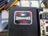
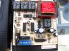
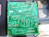
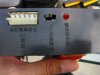
I have a San Long Hun garage remote controller that recently stopped working. When I opened it up there was one IC that was busted. I cannot identify the part because I could not find the broken chip although I am inclined to think that this may be a ULN2003 transistor array IC. Can someone with an identical controller verify this for me?
 

Attachments

  • IMG_6003.JPG
    IMG_6003.JPG
    1.5 MB · Views: 324
  • IMG_6002.JPG
    IMG_6002.JPG
    1.5 MB · Views: 330
It could be a ULN2003. It would be easier to confirm if you had a picture of the bottom of the PCB also. That way we could see how it was wired. Also post the part numbers of the two ICs closest to the ULN2003 as I can't make them out (I think one is a 4013). However, there could also be something else wrong with the circuit which caused the ULN2003 to fail in the first place.
 
Last edited:
Well, I tried installing a ULN2003 and when I powered the unit up, the STOP and UP relays clicked, as well as the solo relay that is close to the power transformer. The two chips that are close to the busted one are TC4013 and TC4028. The chip close to the VD5013 is a TC4030. In the attached photo the one with a circle is the power entry going to the transformer and the boxed ones are the SPDT relays. I scoped the output of the receiver section and everytime I press buttons on the remote, I get a signal, which leads me to believe that the receiver section is OK although there is no relay activity. It may be that the OEM part is not a ULN2003. Any input or comments will be highly valuable.
 

Attachments

  • IMG_6004b.JPG
    IMG_6004b.JPG
    408.4 KB · Views: 326
  • IMG_6005.JPG
    IMG_6005.JPG
    1.3 MB · Views: 333
The one problem that I have experienced with garage opener circuit boards is lightning strikes. I don't recognize any MOV protector components on your board. If the problem is in fact lightning, or an electrostatic/magnetic disturbance, there could be more than one part that is malfunctioning.

In my case, a local dealer replaced the circuit board ... no cost. Check with the factory which made the board.
 
Looks like lightning or mains voltage spike judging by the blast marks on the PCB :eek:

Good spike protection is critical. I don't even see a fuse on that PCB.

sPuDd..
 
Yes, this problem came out after a lightning storm. What I really need is to know the exact part number and from there I can fix this board. The 4013 flip flop, 4028 bcd to decimal decoder, and the 4030 xor gate are all cheap to replace and easy to test off board but if the busted part is not the correct one, then this board won't function as intended. Hopefully somebody, somewhere, has this same unit and would be able to share the info that I need about this IC. By the way, I tried a search for San Long Hun but came to a dead end. It seems that this company does not exist anymore.
 
Last edited:
At a glance, it does look like the blown IC is a ULN200x series IC. Have you checked that both IC1 and IC2, the two voltage regulators, are outputting the correct voltages? But if the VD5013 is blown, then you are probably out of luck. You can check the VD5013 by pressing buttons on the remote. Pins 10,11,12,13 & 17 should change as you press different buttons on the remote; I think pin17 will always toggle but the Japanese datasheet is very vague. Pin 14 should be the data input stream from the the receiver.
 
Hi: The voltage regulators are OK. As for the VD5013, only pin 12 changes as I press buttons on the remote controller. I get a signal on pin 14 from remote presses. The datasheet really does not give us much to work with (i.e., D0 to D3 states for different programming pin configs; what is V.T. ?). I will try to see if I can find a VD5013 to check if pin 12 only changes or not. Info on the busted part though is still much anticipated.
 

Attachments

  • VD5012_5013_5014.pdf
    83.1 KB · Views: 356
Status
Not open for further replies.

Latest threads

New Articles From Microcontroller Tips

Back
Top