Continue to Site

Welcome to our site!

Electro Tech is an online community (with over 170,000 members) who enjoy talking about and building electronic circuits, projects and gadgets. To participate you need to register. Registration is free. Click here to register now.

  • Welcome to our site! Electro Tech is an online community (with over 170,000 members) who enjoy talking about and building electronic circuits, projects and gadgets. To participate you need to register. Registration is free. Click here to register now.

Safety interlock module

Status
Not open for further replies.

wilfredmike

New Member
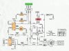
I need a safety interlock module for an old lawn mower. The module is no longer available. The module senses if the brake swithch and seat switch & ect. are ingaged or not inguaged. For example, if you are not on the seat and if the brake is not set the interlock module will activate the kill switch and not allow you to start.
I can connect the brown and green wires and make the mower start, but would like to keep the safety interlock in place.
I have attached the schematic that showes the circuit. Can someone tell me how to make a sensing module to replace the interlock module?
 

Attachments

  • Schematic_showing_safety_interlock_module.psd.jpg
    Schematic_showing_safety_interlock_module.psd.jpg
    94.6 KB · Views: 3,315
I'll make the assumption that the engine is killed by grounding the black wire. This is typical in small engines, i.e. grounding the magneto to kill ignition. So: Kill=Black wire grounded, Run=Black wire open

The Green wire is the primary ground for the starter solenoid. Also, since the seat switch is normally Open, we can deduce that the Brown and Green wires must be grounded to for the mower to start and run.

All you need then, is a circuit that keeps the Black wire open (not grounded) as long as both the Brown wire and Green wire are grounded. If either the Brown or Green wire is not grounded, the Black wire should be grounded.

I'd do this with relays, as in this circuit I'll try to attach. Choose R1 and R2 according to the requirements of the relay coil. They could also be the same resistor. The relays keep the Black wire grounded (kill) unless both relays are energized by having their coils grounded by the Brown and Green wires. You could do the same thing with semiconductors but that is a horrendous electrical enviornment....keep it simple.

Be sure to verify my assumption that Kill=Black wire grounded.
 

Attachments

  • mow_intlk.gif
    mow_intlk.gif
    3.4 KB · Views: 1,535
I'll make the assumption that the engine is killed by grounding the black wire. This is typical in small engines, i.e. grounding the magneto to kill ignition. So: Kill=Black wire grounded, Run=Black wire open

The Green wire is the primary ground for the starter solenoid. Also, since the seat switch is normally Open, we can deduce that the Brown and Green wires must be grounded to for the mower to start and run.

All you need then, is a circuit that keeps the Black wire open (not grounded) as long as both the Brown wire and Green wire are grounded. If either the Brown or Green wire is not grounded, the Black wire should be grounded.

I'd do this with relays, as in this circuit I'll try to attach. Choose R1 and R2 according to the requirements of the relay coil. They could also be the same resistor. The relays keep the Black wire grounded unless both relays are energized by having their coils grounded by the Brown and Green wires. You could do the same thing with semiconductors but that is a horrendous electrical enviornment....keep it simple.
 

Attachments

  • mow_intlk_221.gif
    mow_intlk_221.gif
    3.4 KB · Views: 837
Yes , you are correct in that the black wire is the engine kill switch.
Thank you for your help, I will try the circuit out and see if it works OK
Thanks.
 
Wilfred,

After having another look at it, I'm not sure the circuit I gave you will work. I'm sure that the relay for the Brown wire is correct, but I think the relay for the Green wire will cause some trouble. Here's why: the Green wire must be grounded for the engine to start (gets to ground through the blade switch and the brake switch to the Brown wire), however once it's started and you put the blades down or take the brake off, the Green wire will be floating...in this case my circuit will kill the engine. To be honest, I can't see why the Green wire goes to the interlock module. My suggestion is to forget the Green wire and just use the relay on the Brown wire to ground/open the Black wire.

Sorry for the confusion. :?
 
Well, I am responding to this email before I can see if I come to the same conclusion as you. I just don't have the time right now to look it over. I do no that I am able to crank and use the mower by just connecting the brown and green together. Everything works, but you are able to start in gear, blade enguaged and brake off. Thanks for your time, I will try your suggested circuit. Thanks.
 
Status
Not open for further replies.

Latest threads

New Articles From Microcontroller Tips

Back
Top