trennonix
New Member
Hello,
i got a Tx and Rx that i removed from my radio controlled car and i seperated them from the decoder and the encoder in order to place my own.
My question is: How do i remove the white noise in order to get a clear zero or a clear one, just so that a PIC could decode the signal.
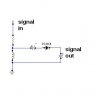
Peak to Peak, the signal is at 1.5V
And what sort amplification should i add?
How should i modify the signal in order for the PIC to differenciate between a one and a zero???
i got a Tx and Rx that i removed from my radio controlled car and i seperated them from the decoder and the encoder in order to place my own.
My question is: How do i remove the white noise in order to get a clear zero or a clear one, just so that a PIC could decode the signal.
Peak to Peak, the signal is at 1.5V
And what sort amplification should i add?
How should i modify the signal in order for the PIC to differenciate between a one and a zero???


")
