Continue to Site

Welcome to our site!

Electro Tech is an online community (with over 170,000 members) who enjoy talking about and building electronic circuits, projects and gadgets. To participate you need to register. Registration is free. Click here to register now.

  • Welcome to our site! Electro Tech is an online community (with over 170,000 members) who enjoy talking about and building electronic circuits, projects and gadgets. To participate you need to register. Registration is free. Click here to register now.

Running out of PWM outs on PIC16F876A

Status
Not open for further replies.

raitl

New Member
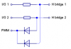
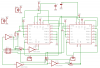
I want to run two cordless drill motors through MC33886DH-s with PIC16F876A. The MC33886DH uses two inputs to control the direction of the motors, but the PWM is applied to the pin, that is LOW at the time. So when running in one direction, I need to PWM on pin, when running in reverse - another. And since I want to run 2 motors, I'd need 4 PWM outs. Is there any other way to solve the problem, aside from getting a new pic?
 
but I need to PWM two pins alternately.

Say I use PinA and PinB for controlling one motor. So when moving forward, I'd keep PinA HIGH and PWM PinB. And for reverse I need to hold PinB HIGH and PWM PinA.
 
look through the microchip website at some of the larger 18F series chips ... many of them have "motor control" modules, called ECCP or Enhanced Capture Compare PWM, where the PMW module is capable of driving multiple H-bridge chips in various configurations (more pwm outputs)
 
yeah well that's what I wanted to know... if there was any other way, except changing PIC's.. So I guess I'm going to have to look for an alternative H-bridge for my motors.
 
ok..I started wondering something... I would be set, if there was a way to switch I/O-s with an extra logic gates or something like that.

Or maybe with a couple of transistors? Create a low power H-bridge, use PIC PWM pin for one input, take +5V for the other and a second PIC pin to control the direction of the small H-bridge? That could work, couldn't it?
 
The usual way is to apply the PWM to an 'enable' input on the H-bridge, and use either one or two I/O lines to set the direction - most small H-bridge IC's have this facility!.

Basically you need to design your H-bridge accordingly, the two PWM channels should be all you need!.
 
Nigel Goodwin said:
The usual way is to apply the PWM to an 'enable' input on the H-bridge, and use either one or two I/O lines to set the direction - most small H-bridge IC's have this facility!.

I know that, and the other two H-bridge IC's I have, both have that facility. But the 5Amp one that I need to use, is different at that.
 
raitl said:
Nigel Goodwin said:
The usual way is to apply the PWM to an 'enable' input on the H-bridge, and use either one or two I/O lines to set the direction - most small H-bridge IC's have this facility!.

I know that, and the other two H-bridge IC's I have, both have that facility. But the 5Amp one that I need to use, is different at that.

I still think that's FAR too small anyway! :lol:
 
well if they crash and burn on me, then I'll get some high power MOSFETS and put together a new H-bridge. But since these are the options I have right now, I'll have to find a way to get the job done with those IC-s.

Someone recommended to use 74HCT00-s to toggle the PWM and the second PIC output. But I have no idea how to accomplish that... :oops:
 
Its simple look have two normal I/O pins drive the H brihgt trough a resistor. Then have an diode to the PWM pin.So the at the PWM signal will pull down the I/O pin.So you make the I/O go high an the PWM will pul it down trough the diode.

This is the simplese way to drive an H bridge whith no enable fuction.

An more profesional method would be AND gates.
 
Heres an schem
 

Attachments

  • pwm1_197.png
    pwm1_197.png
    1.9 KB · Views: 741
ok, so this should work?

SL1 and SL2 - motor outs
SL3 - motor and H-bridge power
SL4 - +5V power
SV1 - to PIC
 

Attachments

  • circuit_347.png
    circuit_347.png
    66.8 KB · Views: 771
Status
Not open for further replies.

Latest threads

New Articles From Microcontroller Tips

Back
Top