Electro Tech is an online community (with over 170,000 members) who enjoy talking about and building electronic circuits, projects and gadgets. To participate you need to register. Registration is free. Click here to register now.
Welcome to our site! Electro Tech is an online community (with over 170,000 members) who enjoy talking about and building electronic circuits, projects and gadgets. To participate you need to register. Registration is free. Click here to register now.
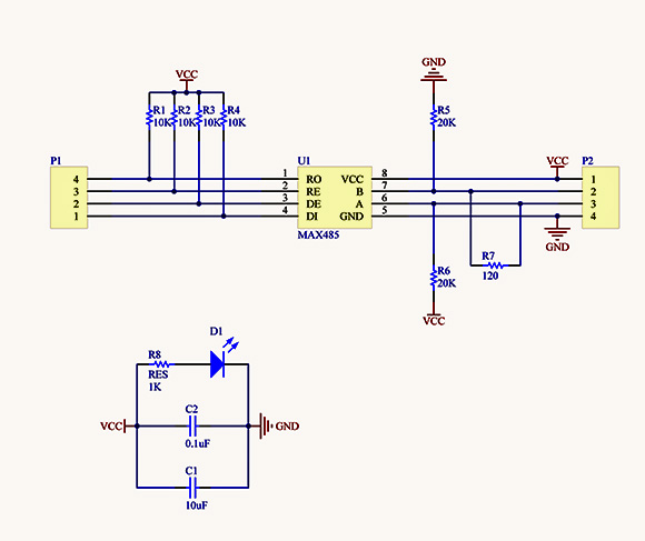
A RS485 to TTL module has schematic below.
Connecting DE to pullup causes the output driver enable. But this risks conflicts with the bus when other connected bus devices also have their output enabled.
Should DE not be connected with pull down (10k to ground)?
Connecting DE to pullup causes the output driver enable. But this risks conflicts with the bus when other connected bus devices also have their output enabled.
Should DE not be connected with pull down (10k to ground)?
What you say is correct, and would be a problem if the module was used on its own without being connected to some device such as a microprocessor which was controlling the comms line.
In a practical application, pins 2 and 3 of the MAX485 would be connected together and controlled by a digital out put from the micro.
When that digital output is low, the MAX485 will have the Rx enabled and the TX disabled,
and,
when that digital output is high, the MAX485 will have the Rx disabled and the TX enabled.
IMO that would have been a better arrangement. With DE pulled down R5 and R6 would establish a default state.
As it is, when the devices first power up (or reset), since DE is pulled high all the connected devices will drive the bus until the uC initializes the state of the IO pins. At least they will all try to drive it to the same level since DI is also pulled high, but this isn't the greatest of conditions.
You could add an external pulldown on the DE signal but it would have to be pretty stiff to override R3 (10K), say 1K or so.
This site uses cookies to help personalise content, tailor your experience and to keep you logged in if you register.
By continuing to use this site, you are consenting to our use of cookies.