upand_at_them
Active Member
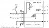
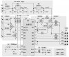
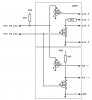
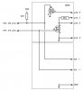
I'm thinking about using transistors (2N3904) in my application for level shifting the RS232 signals instead of using a MAX232. Much the same way a BASIC Stamp does it.
Is either one inherently more power hungry than the other? Can the transistor method be made to consume less power than a MAX232?
The reason for considering this is cost and my PIC application will most likely be run at 3V. And I also want to have a choice of two serial connections to it: 1) TTL level signals from another PIC or a GPS, and 2) my PC or laptop.
Mike