Electro Tech is an online community (with over 170,000 members) who enjoy talking about and building electronic circuits, projects and gadgets. To participate you need to register. Registration is free. Click here to register now.
Welcome to our site! Electro Tech is an online community (with over 170,000 members) who enjoy talking about and building electronic circuits, projects and gadgets. To participate you need to register. Registration is free. Click here to register now.
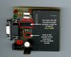
It is unlikely to be MAX232 as this IC needs four external electrolytic capacitors to work and the capacitors are not visible in the image. I would guess the IC is a microcontroller, based on the two crystals, 330 ohms resistors, and the two LEDs near it.
Are you trying to repair it? If you want to build it, you're in for a big surprise.
There are also two crystals on the board, one is 6.000MHz and the frequency of the other not readable from the image.
You can buy these crystals no problem, but the presence of crystals indicate hiding somewhere there is/are microcontroller(s) or custom made IC which you cannot obtain or obtainable but won't work without firmware code .
where did this card reader thing come from? it looks like a prototype or hand made, deff not mass produced, who uses that many TH components
heh, i type phoenix smouse into google and I get lots of info for hacking satellite receivers ...
so, my guess is it's a pic micro, since smartcards are PIC based, this board is most likely just a 'smart' PIC programmer (ICSP) with a smartcard socket
there aren't too many current model 14 pin PIC's out there, and the pin-outs are pretty much the same across all of 'em, just different features and amounts of memory ... if I had to hazard another guess, I'd go with a 16F630
but whatever is on there is likely code protected, so its not like you'll be able to duplicate the firmware to a new chip or anything
The PIC is probably hiding under the black plastic in the form of a black blob.
OP already told us the power pins of the visible 14-pin DIP is 7 and 14 so it is unlikely to be a PIC. It could well be a 74HC04 used as oscillator for the 3.579545 MHz crystal.
The extra resistor on the black plastic does not exist but was placed there using image editing software.
As suggested it's probably just a TTL buffer, and it may well be designed to connect to a PARALLEL port and not a serial one? - a suitable lead will have been provided with it.
I got it. The PIC is under the black plastic but on the inserted card.
The components are supporting chips act as signal source or buffer. I still think it is a simple serial port interface using resistors and transistors.
I got it. The PIC is under the black plastic but on the inserted card.
The components are supporting chips act as signal source or buffer. I still think it is a simple serial port interface using resistors and transistors.
Sorry, I didn't realise you didn't know that there is a PIC on the inserted card?, which is the complete reason for the programmer :lol:
Many of the cards also have an EEPROM on them as well, but there's no external access to it, you have to program the PIC to transfer data to the EEPROM.
BTW, you might be interested to know that the May 2006 issue of EPE has a card reader/writer as a project, it uses a MAX232 and TWO 7407's, and connects to the serial port.
Hi
I have the same programmer
and Itried to make another with the two Ic(max232 &74 hcoo) with simi conductor in circuit with no. (bat41) but failed to found it
the programmer (phoenix&smouse) we write about it . i expect that the Ic is 74hc00 but the transistor is the important part that it the alternative part of the two parts( max232 & bat41) on other programmers
sorry for my week lang.
This site uses cookies to help personalise content, tailor your experience and to keep you logged in if you register.
By continuing to use this site, you are consenting to our use of cookies.

")