Continue to Site

Welcome to our site!

Electro Tech is an online community (with over 170,000 members) who enjoy talking about and building electronic circuits, projects and gadgets. To participate you need to register. Registration is free. Click here to register now.

  • Welcome to our site! Electro Tech is an online community (with over 170,000 members) who enjoy talking about and building electronic circuits, projects and gadgets. To participate you need to register. Registration is free. Click here to register now.

Round off waveform edges from mosfet simulation

Status
Not open for further replies.

mik3ca

Member
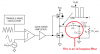
Ok, so I did more tweaking and I finally found the opamp sim files, but I had to make a substitution for the IRF9530. So far, things work better but the volume is a bit too low (maybe because my speaker is 1/2 watt). In the circuit here, I used an 8-ohm resistor to simulate the speaker since the speaker is 8-ohms.

As you can see, the waveforms are squared when amplified. Is there a way to round them so they look almost like the original (but amplified)?

I may be tempted to reduce the resistor values but if I do then I might get more sound volume but then higher battery consumption may be required. Is there another way to increase the volume?

The audio input comes from the analog output of the ISD1760py chip and someone said that output is 1 volt peak-to-peak.

circuit.png
 
You have no feedback. Feedback essentially connects the amplifier output back to the amplifier input to insure the output tracks the input. Right now, your output is saturating (over amplifying) - the waveform is limited (clipped) by the power rails ground and Vcc.

Also, your RST pin on 555 should be at Vcc.
 
CV needs a cap to ground, and rst needs to be at Vcc. at the moment you are only getting the audio feeding the comparator. the 555 is not free-running. also, you want the 555 to generate a triangle wave, so don't use the OUT pin to feed the comparator, use the TRIG pin.
 
Right now, your 555 is set up to run at 600kHz (way too high).

Your 555 is set up to output 60% duty cycle (you should be closer to 50%

(Fix both by using a 1nF cap and change R2 to 10k)

Then, use Pin 6 of 555 to feed the comparator instead of pin 3

(Also, pull RST up to Vcc)
 
Right now, your 555 is set up to run at 600kHz (way too high).

Your 555 is set up to output 60% duty cycle (you should be closer to 50%

(Fix both by using a 1nF cap and change R2 to 10k)

Then, use Pin 6 of 555 to feed the comparator instead of pin 3

(Also, pull RST up to Vcc)

According to http://www.ohmslawcalculator.com/555-astable-calculator, if R1=2.2K and R2=10K and C=1nF then frequency is 65 kHz. Thats only 3x the highest audible frequency. Skouldn't I select a frequency thats at least 10x?
 
You still show the comparator input as coming from pin 3 of the 555, not pin 6.
 
Ok, so I did get sawtooth output from the 555 but the output looks substantially worse. The red is the input wave and when I measured blue alone, the output is in the microvolt range.

Is there a way to make a sawtooth generator with an LM393 then maybe I can eliminate the need of a second (555) IC?

circuit.png
 
I found info here: **broken link removed**

but somehow I need to reduce the output power since my speaker is 0.5W. I tried replacing the output inductors with 120 ohm resistors and the volume is way too low.
 
Since it looks like you are trying to make a class-D audio amplifier using PWM made by comparing a triangle waveform with the audio then you should say so.
Your new schematic is too small to see anything. I attach how it looks when enlarged.

The audio input to the comparator should be at half the supply voltage but yours is too high causing the output to be at 0V. The triangle waveform should also be near half the supply voltage or at the same voltage as the audio input.
The LM393 is a low power comparator. Low power ICs cannot work at high frequencies and your triangle wave is 500kHz to 600kHz. Try a faster comparator or 60kHz instead.
Your lowpass filter is too simple with only an inductor. add a capacitor to ground between the inductor and the output coupling capacitor to make a better filter.
 

Attachments

  • PWM class-D amplifier.png
    PWM class-D amplifier.png
    18.1 KB · Views: 92
  • class-D amplifier.png
    class-D amplifier.png
    15.5 KB · Views: 105
Is there a way to make a sawtooth generator with an LM393
Yes. Here's a triangle generator, but you could esily modify it (diode across R3) to give a sawtooth if you really want that.
TriangleGen.PNG
 
ok so now I made the divider for -ve input at 50% (based on resistors), and I lowered the 555 frequency to just under 60khz and the input audio is 4khz. I added a 22 ohm resistor to limit output current. I'll worry more about output filtering after the rest of the circuit is perfect. Heres the results with square wave. vn007=square wave output from 555 vn004=input audio, vn003=output (measured at top of R7)

circuit.png

circuit2.png


and here's the results using the 555 timer as a triangle waveform generator

circuit3.png

circuit4.png

so to me triangle waveform in this case isn't doing anything
 
you need to match the DC level on the triangle wave output and the audio input on the comparator side of the coupling capacitor (C3). this means the comparator input for the audio needs to be biased at 2.5V like the triangle input.
 
Your red, green and purple waveforms are not labelled.
It is obvious that the triangle waveform is the signal to the (+) input of the comparator averaging +2.5V but the red might be the (-) input of the comparator before C3 has charged??
Then the (-) input of the comparator is still 0V then the output of the comparator is as high as it can go and the output of the Mosfets is as low as they can go which might be the purple waveform??
C3 will be near a full charge in 90ms but your 'scope begins immediately and ends long before C3 is charged. Start the SIM at 100ms and it will probably work fine.

Why is the output LC lowpass filter missing?

Why do you have R7 that attenuates the signal to the speaker to only 0.27 times? When R7 is replaced with a piece of wire then the value of C2 must be increased to pass low audio frequencies.
 
A speaker volume control is never used between the output of an amplifier and the speaker like your R7 because then the extremely low output impedance of the amplifier cannot damp the speaker resonance then the speaker resonates like a bongo drum.
The volume control is always at the input of an amplifier.
 
I'm trying to make it so that alot of power isn't drawn. By adding the 22 ohm resistor, I reduced power consumption to about 200mA which is OK. I'm running this off of batteries and I don't want my 4000mAH batteries to die in 1 hour.

So I've been tinkering more and could probably get away with something like this but the waveform isn't 100% perfect, but its somewhat better than what I had before.
circuit.png
 
200mA and 5V is 1W so your circuit is wasting a lot of battery power. A class-D amplifier uses PWM which has an efficiency of about 90% so it would use only 23mA for its maximum output of only 0.1W into the 30 ohms (22 ohms plus 8 ohms) load.
The wasted power is caused because the low power comparator switches too slowly and does not produce the high current required to quickly charge and discharge the high input capacitance of the Mosfets. A Mosfet driver circuit is missing. Also your circuit is missing the "deadtime" between switching high and low that was mentioned in the article you posted then both your Mosfets are turned on at the same time producing a short across the battery each time they switch.

Your new circuit is linear, not using PWM and its output distortion is absolutely horrible.
 
It turns out I was measuring the output wrong. The output is sortof better now, but what should I replace that LM393/LM339 with since someone said that IC is wrong for what I'm trying to achieve?

circuit.png
 
PWM is made with a triangle waveform, not with a square waveform.
The article you posted recommends the MAX941 single, MAX942 dual or MAX944 quad comparator with a 6.5V supply.
 
Status
Not open for further replies.

Latest threads

New Articles From Microcontroller Tips

Back
Top