Continue to Site

Welcome to our site!

Electro Tech is an online community (with over 170,000 members) who enjoy talking about and building electronic circuits, projects and gadgets. To participate you need to register. Registration is free. Click here to register now.

  • Welcome to our site! Electro Tech is an online community (with over 170,000 members) who enjoy talking about and building electronic circuits, projects and gadgets. To participate you need to register. Registration is free. Click here to register now.

Rooky fm radio builder

Status
Not open for further replies.

colinmarais

New Member
Hi everyone. I am a VERY inexperienced electronics fanatic (If you can call it that) and want to start with my first FM radio. I have searched the web for a good diagram but they are few and far between. An friendly expert suggested the "radio shack special" (google it). I need some help please!

Question one: How important is it to place the components in relation to each other on the PCB? (I cannot make a custom board. Have to use pre drilled board - looks like a mesh?) So, can I place the components anywhere as long as the circuit is complete and according to the origional diagram?

Question two: How thick is 30 gauge magnet wire in mm?

Believe me, I have more Q's, but will post them a bit later if you all don't mind.

Thanks a mil
colin:)
 
At these frequencies component placement is very important.
30 gauge is 0.25 mm diameter.
 
More Q's

Thank you sir for the reply. you stated that at these freq the placement is very NB. any specific advice?

Question 3: They stated I need a 10K and 1K horizontal style trimmer. The ones I got from the store are HUGE but still have the values 10K and 1K printed on them. Will this effect the radio?

Question 4: I bought all the components but just got a bag back. I have a good idea which are the resistors and which are the capacitors. I also figured out that the small ceramic caps have a code. ie 402 means 40 plus 2 zero's. thus 4000pF and thus 4nF and 0.004uF. I came across a problem. How will a 10pF look. and what does 4R7 mean?

Question 5: Any formula for the gauge/mm conversion. How much difference will it make if the wire I use is for instance 0.35mm? Or is it the same as the component placement.
 
3) The pots might be OK. Depends on where it is in the circuit.
4) 10pF will be small, might not be marked. It's the one left over after you've identified the rest. 4R7 is 4.7 ohms. Lots of people prefer this because the dots get lost in photocopying.
5) I simply Google awg mm. Wire size is important if you're winding a coil.
 
re:Question4

The gentleman at the shop said the nr is 102 or 103, according me that is not quite correct? is it possible to send a picture to you? It is difficult to describe the one component...:confused:
 
It is possible to attach a photograph to a forum post. I recommend no larger than 1024 x 768 pixels. The forum instructions are good.

Do you have more than one unidentified device?
 
Hi Colin,
The project has a double-sided pcb layout that should be used. The project might need to have its parts values changed if you make it on perforated board.

The potentiometers are small trimpots.
 
Thanks guys. I have 1 or 2 unidentified components. I will try to attach a pic. Wow, you guys are getting me depressed. Each time there is something new I do not know about... :eek: 
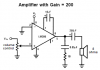
Audioguru: Can you send me some recommendations please? I will also attach the diagram if I can > Link: Radio Shack Special
 
Thanks guys. I have 1 or 2 unidentified components. I will try to attach a pic. Wow, you guys are getting me depressed. Each time there is something new I do not know about... :eek: Audioguru. Can you maybe give some suggestions...
 
Hi Colin,
The Radio Shack Special is completely different from a "real" FM radio.
It uses a "regenerative" circuit. Another similar simple radio circuit is a "super regenerative" circuit.
A real radio uses a more complex "super heterodyne" circuit.
You can read descriptions of the circuits in Google.

Patrick has his own website with improvements to this original circuit but his website is down.

Here is a "super regenerative" radio project:
**broken link removed**
It is super because it automatically adjusts its sensitivity over a small range of signal strength. Then it does not have a sensitivity adjustment pot like in the Rasdio shack Special project.
 
will give it a go tonight. thanks. Just one Q. How do I connect the earphones or speaker. I do not know that simble (where it says audio out to amplifier) Thanks
 
The Superregenerative Radio Receiver project has another page that describes a horrible little power amplifier project to drive headphones or a speaker.
An LM386 little power amplifier IC as used in the Radio Shack special project can be used instead and performs much better.
 
Thanks audioguru. Your wonderful! Any specific diagram i can use? I have that ic but no idea how to use it as you suggested. Please!
 
Hi Colin,
The Radio Shack Special and millions of other circuits use the manufacture's diagram in the datasheet for the LM386 little power amp. The Radio Sshack Special has a 0.001uF capacitor added from pin 3 (input) to ground.
Here is the diagram in the datasheet:
 

Attachments

  • LM386 in RSS project.PNG
    LM386 in RSS project.PNG
    11.3 KB · Views: 145
Use the 1nF capaitor, it will stop RF from entering the LM386 which would produce distortion and make wierd noises. It won't make much difference to the audio since the cutoff frequency is above the FM audio band.
 
Status
Not open for further replies.

Latest threads

Back
Top