Electro Tech is an online community (with over 170,000 members) who enjoy talking about and building electronic circuits, projects and gadgets. To participate you need to register. Registration is free. Click here to register now.
Welcome to our site! Electro Tech is an online community (with over 170,000 members) who enjoy talking about and building electronic circuits, projects and gadgets. To participate you need to register. Registration is free. Click here to register now.
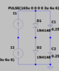
I am attaching the full circuit. The input currents get subtracted due to opposite polarity and then current is converted to a voltage. But my question is output remains the same with and without diode. why?
Both current sources are considered to be floating so I1 only forms a circuit through diode D1 (And C1 during transitions.) There is no way it can provide any input to the op amp.
For the second point you need to read up on op amps to understand how they behave. As the non inverting input is connected to ground it attempts to keep the inverting input at the same potential. (I.E ground) An op amp will be considdered to have an infinite input impedance so no current flows in or out of it's input. the only place I2 can go is through is through R3. So for that to happen the op amp output must go to a negative voltage which produced a current of 150 uA (I don't understand the terminology of your pulse description but I am assuming the current is 150 uA) So this voltage must be - 150 mV. Diode D2 does not pass any current as there is zero volts across it. The capacitors will have to be taken into consideration at the transitions of the pulse. If you understand this description of the DC behavior you can then do the calculations which takes into account the reactance of the capacitors.
The net current difference between the two sources is 15uA.
That current is produced by just 15 millivolts across the 1K resistor.
The signal voltages never get anywhere near the 600mV or so needed for the diodes to conduct.
With steady-state conditions, the capacitors do nothing at all.
If the photo diodes behave as current sources then you will get an output in proportion to the difference in currents What is the purpose of the diodes and capacitors ? If you tell us exactly what you are trying to achieve we will be able to assist you better.
When D1 and D2 become forward bias and reverse bias?
Photodiode operates in reverse bias. So, Diodes (D1 and D2) are in reverse bias condition? How to say theoretically?
This site uses cookies to help personalise content, tailor your experience and to keep you logged in if you register.
By continuing to use this site, you are consenting to our use of cookies.