Continue to Site

Welcome to our site!

Electro Tech is an online community (with over 170,000 members) who enjoy talking about and building electronic circuits, projects and gadgets. To participate you need to register. Registration is free. Click here to register now.

  • Welcome to our site! Electro Tech is an online community (with over 170,000 members) who enjoy talking about and building electronic circuits, projects and gadgets. To participate you need to register. Registration is free. Click here to register now.

Roland SPD-20s, differentiators, and diodes question

Status
Not open for further replies.

Torben

Well-Known Member
Hi all,

Another question (on my foosball scoreboard, of course) which comes off the end of another thread I had (https://www.electro-tech-online.com/threads/transistor-switching-question.28346/).

The circuit I refer to below is attached.

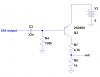
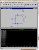
Basic idea: I am trying to both turn on a 12V/20mA lamp (U1), and trigger a sample from my SPD-20 drum pad. The lamp works fine. (Background: you can trigger the SPD-20 using a piezo directly wired into a trigger input; that's the effect I'm trying to get for my pulse into the SPD-20.) The trouble is that my input pulse is in reality from a 555 configured as a 3-second-on one-shot, which turns on the 3904 controlling the lamp for ~3secs. Oddly, the SPD-20 triggers at the end of the pulse, not the beginning as I would have expected.

In short: someone scores. Immediately, a lamp should light up and a pulse should trigger a sound from the SPD-20. The lamp should stay on for around three seconds. (So far, this all works fine.) The problem is that the SPD-20 is triggered at the end of the three seconds.


(The following paragraph is just background and can be safely skipped.)
I thought it was odd that the SPD-20 would trigger at the falling edge of the pulse, so I first reversed the polarity of the plug into the SPD-20. That achieved the desired effect, until I plugged in the next input and found that both triggered together when they should trigger separately. I tested the SPD-20 trigger inputs (4 of them) with an ohmmeter and found that my original grounds on it had been correct, and I now had my signal inputs connected to SPD-20's common. So I have gone back to the original wiring, which still triggers on the falling edge.


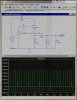
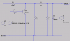
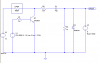
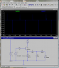
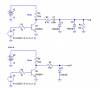
So I tried an RC differentiator: see the second attachment. I figured if I could just get a spike at the leading edge of the 3-second pulse, I'd be golden. No such luck. It still triggered at the end of the pulse. (Note: the 0.6V positive spikes are the result I want; the -1.2V spikes I do not want. Trace Vn007 is from the junction of D2 and R3.) I added the diode D2 to try to get rid of the negative spike generated by the differentiator, but that doesn't appear to work either in the sim or in real life. So I'm lost.

Anybody familiar with SPD-20 triggering, or have any insights into the rookie mistake(s) I'm making here?


Thanks in advance,

Torben
 

Attachments

  • question_about_transistor_switching_diode_sim_2.png
    question_about_transistor_switching_diode_sim_2.png
    43.1 KB · Views: 245
  • question_about_transistor_switching_rc_diff_sim_1.png
    question_about_transistor_switching_rc_diff_sim_1.png
    64.6 KB · Views: 255
Last edited:
gramo said:
I'm thinking you could do this whole project with minimal parts/ease of designing by using a PIC.. just a thought

Hi Gramo,

Thanks for the response, but yeah, I know. I've actually got a couple of 8051 compatibles here I could use, and an ARM SBC running Linux if I really wanted to get easy. My whole idea here is learning logic ideas from the ground up. More or less the same reason I felt that learning assembly was a good idea when I decided to become a programmer. (Parts of the circuit I decided to implement in discrete transistor logic, if that makes any sense--at least now I know why it works).


Thanks for the idea, though!

Torben
 
You need the other polarity, apparently. Below are differentiated and undifferentiated outputs. You can probably use the undifferentiated one. It will run a little current throughyour lamp when it is off, but should not be enough to light it.
 

Attachments

  • trigger.PNG
    trigger.PNG
    9.4 KB · Views: 268
Ron H said:
You need the other polarity, apparently. Below are differentiated and undifferentiated outputs. You can probably use the undifferentiated one. It will run a little current throughyour lamp when it is off, but should not be enough to light it.

Great, thanks! I'll give these a shot. It'll be a few days before I can work on this thing again, but when I can I'll post my results.


Thanks again,

Torben
 
OK, finally got some time to try this.

Unfortunately, none of the proposed ideas worked. I can only assume that the problem lies elsewhere within my circuit or that my SPD-20 inputs are more complex than I thought (neither idea is out of the question).

Anyway, I now intend to skip this problem for now, and just install some bike bells rung by toothbrush motors, which are essentially pager motors with gearing for a linear striker. I'll be able to get around the SPD-20 interface problem, not endanger my SPD-20, and not have to hook the foosball table to the pads to have it work.

Anyway, someday I'll try this again. But thanks for the tips!


Torben
 
Maybe this would work. It should give you a pulse for each leading edge, the negative-going portion of which might trigger your device. (It might be a bit of overkill, actually.)

You can adjust the output pulse's amplitude by playing with the component values.

You might NEED to adjust the input cap's value, and some of the resistors, depending on the rise-time of your input.

**broken link removed**

Good luck.

Tom Gootee

**broken link removed**

-
 
Actually, the first circuit proposed by RonH does work...almost. It triggers correctly when the light goes on, but also triggers when the light goes off. I'm going to try throwing another diode in series with the output to see if that helps.

More notes when I get a chance.


Torben
 
Torben said:
Actually, the first circuit proposed by RonH does work...almost. It triggers correctly when the light goes on, but also triggers when the light goes off. I'm going to try throwing another diode in series with the output to see if that helps.

More notes when I get a chance.


Torben

I played around with RonH's first circuit in LT-Spice. If you simply remove capacitor C1, the output should stay above zero, instead of being symmetrical about zero, and won't have any negative slope when the light turns off, but will still drop from about 620mv to 20mv when the light goes on. (I was assuming the negative slope was the problem. But if it's looking for zero crossing direction, for example, this won't quite work.)

Actually, it might even be good to put C1 in parallel with D1, instead of removing it, so there'd be a little filtering.

- Tom
 
gootee said:
I played around with RonH's first circuit in LT-Spice. If you simply remove capacitor C1, the output should stay above zero, instead of being symmetrical about zero, and won't have any negative slope when the light turns off, but will still drop from about 620mv to 20mv when the light goes on. (I was assuming the negative slope was the problem. But if it's looking for zero crossing direction, for example, this won't quite work.)

Actually, it might even be good to put C1 in parallel with D1, instead of removing it, so there'd be a little filtering.

- Tom

Hi Tom,

I tried that in ltspice and no joy, unfortunately. I also tried sticking a diode in series just after C1 to try to rectify the output, since I only want the < 0V spike from the differentiator. Haven't tried it in the real world yet but it doesn't work in the sim.

I think I can define my problem a little better now though:

I want to take a +-12V square wave, differentiate it, and discard the positive portion of the resulting signal. I feel like I'm missing something really easy here.

Anyway, sorry I'm going so slowly on this; I've also been messing with microcontrollers in my spare time, of which I have very little since my main project recently has been being a father for the first time. :)

Thanks all for the help so far! Eventually I'll either get this thing working (probably with your help) or else just stick some bells/buzzers on it and drop the outboard sound gear.


Cheers,

Torben
 
So, as I understand it, you want a short pulse on the leading edge of a 3-second pulse. Is this correct? Do you want to develop this from the output of the 555, or from the output of the lamp driver, or does it matter?
Is the 555 running off a +5V supply, and the lamp off +12V?
How long should the output pulse be, what amplitude, and what polarity relative to GND? Is the impedance important?
This should be a simple problem. The problem is, no one knows (maybe you do now?) how your SPD-20 triggers.
 
Hi Ron,

Ron H said:
So, as I understand it, you want a short pulse on the leading edge of a 3-second pulse. Is this correct?

Correct. A 2 or so millisecond negative pulse at around 600mV.

Do you want to develop this from the output of the 555, or from the output of the lamp driver, or does it matter?

Either/or. The 3-second pulse is indeed generated by a 555, the output of which goes to the circuit fragment I originally posted to power the 12V lamp.

Is the 555 running off a +5V supply, and the lamp off +12V?

Sorry, forgot that--yes, this is correct.

How long should the output pulse be, what amplitude, and what polarity relative to GND? Is the impedance important?

A couple of milliseconds should do it. I can alter the length of pulse to which the SPD-20 will respond using its built-in controller, but not up to anything like 3 seconds--it's more of a debounce feature for the trigger inputs.

To recap, I'm trying to generate a ~2ms -600mV pulse.from either a 12V or a 5V square wave.

This should be a simple problem. The problem is, no one knows (maybe you do now?) how your SPD-20 triggers.

No, I still don't, although the manual just indicates voltage thresholds. I don't think Roland wants me to know without a service license. :) That's why I put SPD-20 in the subject line; I've searched the web and the closest I've found so far is people like me who've triggered them using piezos. I have built a set of outboard triggers for the thing by just soldering piezo elements to the ends of guitar cables and just plugging those straight into the trigger inputs, and they work fine--so the inputs are fairly tolerant.

Oddly, I get +5V off the + and - of the first trigger input with nothing plugged in; I assume this is for a special kind of pad. So I'm using both the first and second inputs to test with, since the second does NOT appear to have any voltage across it.

Again, I was having good luck with the first circuit you proposed, and figured I could just insert a diode to rectify away the positive-going pulse generated when the light goes out. Obviously I can't put this after the circuit you posted--my entire signal at that point is just about one diode drop--so I tried putting the diode right after C1, in series with it, but this doesn't appear to work either.

As to the impedance, would an ohmmeter give me a useful reading? Or would I need to open the SPD-20 and work it out by looking at the trigger input section? 'cause I've done that and unfortunately they just go into unknown ICs.


Regards,

Torben
 
You said my original circuit triggered the SPD-20 on both edges. That means that either polarity pulse will work, but it needs to be only on the leading edge. This circuit completely eliminates the trailing edge pulse. It is negative-going to GND, but the quiescent level is about+0.9V. You could AC-couple it into the trigger input, but I suspect this is not necessary.
 

Attachments

  • pulse differentiator.PNG
    pulse differentiator.PNG
    13.1 KB · Views: 182
Maybe this...

Hi Ron,

Thanks for the circuits, but I suppose what I'm really looking for is a way to take this off the part of the circuit that's already built. Sadly that means that pulling another 5V line to it could be problematic.

Something else I've simmed and which looks like it might work with the proper trigger input settings on the SPD-20: I believe Eric Gibbs came up with the original idea: see the attachment. With a positive pulse of ~450mV and a negative of only ~-120mV, I hope to be able to set the trigger input sensitivity to discriminate properly between the two levels.

I have to go feed the kid then hit the hay now, but hopefully I'll get a chance to post an update tomorrow night.


Regards,

Torben

[edit: Argh. Forgot this too: R1, R4, V1, V2, and Q1 are in the existing circuit. R4 represents the lamp.]
 

Attachments

  • trigger_idea.jpg
    trigger_idea.jpg
    97.2 KB · Views: 172
Last edited:
One last gasp. :(

When you said you could trigger off the 555 output, I assumed you could use +5V. My bad. You can use +12V instead of +5. You should also add a resistor in series with the cap to limit base transient current. See below. There is also a circuit in this schematic which develops the pulse from the lamp driver.
 

Attachments

  • pulse differentiator1.PNG
    pulse differentiator1.PNG
    24.7 KB · Views: 189
Hey all...


...and especially Ron H, who has bent over backwards on this one.

Sorry about the long absences and consistently negative replies. However, I think I have identified problems deeper in my original circuit which I may need to address before trying to solve the SPD triggering problem again.

So I'll probably come back to this in the future but I have some more work to do first and I have other projects cooking which I think I can finish sooner.

Thanks again and I hope eventually not to have wasted all the help you've all given me!


Torben
 
Ron H said:
One last gasp. :(

When you said you could trigger off the 555 output, I assumed you could use +5V. My bad. You can use +12V instead of +5. You should also add a resistor in series with the cap to limit base transient current. See below. There is also a circuit in this schematic which develops the pulse from the lamp driver.

Of course, after posting that I was giving up for a while, the damn problem kept spinning around my head.

I may have misspoke--when I said 'either/or', I meant that I don't care whether the SPD triggers from the +5V or the +12V, not that it might have to trigger from either. I apologize for not being clearer.

Anyway, I ended up solving the problem, I think. My current idea works both in LTSpice and in the real world; I've now tested it on all 4 inputs on the SPD-20. An image of the circuit and its .asc file are attached.

What I (think I) did was : I changed the source of the differentiator from a positive-going edge to a negative-going one.

[edit]
R2 is there to bring the 12V down to around 5V.
[/edit]

I used a high cap-to-resistor ratio for C1 and R3 to make the spike fairly broad, to attempt to imitate a piezo hit a bit more closely (ms instead of ns). After that I put a diode to ground to clamp the positive-going spike--in this case, a Schottky so I can pull the positive-going spike a bit closer to ground.

V3 is meant to imitate trigger input 1 on the SPD, which presents about +4VDC and measures about 100K ohms.

Have I accurately described what is happening here? It seems to make sense...:)


Thanks again, all!


Torben
 

Attachments

  • spd_trigger_1.png
    spd_trigger_1.png
    10.1 KB · Views: 196
  • testing_spd20_interface_8.asc
    2.1 KB · Views: 142
Last edited:
Why couldn't you take the output right off the lamp driver (see below)?
The circuit you posted can't be the lamp driver, because of the 470 ohm resistor, unless you want to keep the lamp warm (and possibly glowing dimly).
 

Attachments

  • pulse differentiator2.PNG
    pulse differentiator2.PNG
    13.3 KB · Views: 186
Ron H said:
Why couldn't you take the output right off the lamp driver (see below)?
The circuit you posted can't be the lamp driver, because of the 470 ohm resistor, unless you want to keep the lamp warm (and possibly glowing dimly).

Cool, that does the trick nicely. The answer to your question is probably something to do with the time of night that I finally got the thing working.

The 470 to ground did look suspicious to me, but I didn't worry too much about it last night since it didn't make the lamp glow. And now you've solved pretty much my last problem!


Thanks again,

Torben
 
Status
Not open for further replies.

Latest threads

New Articles From Microcontroller Tips

Back
Top