Torben
Well-Known Member
Hi all,
I have built a foosball scoreboard which works fine for me. It is based on TTL logic for the counting and LED display, and 555s for the trigger debouncing and win detection. The 555s trigger 3904s to light red 12V/20mA lamps when either player scores, and blue ones when either player wins. Now I want to add outputs which I can plug into the trigger inputs of my SPD-20 (Octapad-like unit with internal sound generators).
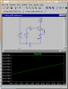
The circuit segment in the first attachment shows how I am currently switching the lamps in the bottom half of the image, and how I think I might trigger the SPD-20 in the top half. I tested the inputs on the SPD-20 and I like the sensitivity range it shows using 0.9V pulses, so that's what I set the voltage divider to for that section. (Actually, here's a side question: at the behest of someone I'm not sure I trust too much, there is also a 104 ceramic cap across each 3904's emitter and collector, and a 1n914 diode across each lamp--I think the diode is there because I mentioned the thought of powering small motors to ring bells instead of using the SPD-20. What are the caps doing there? Anything? It does work with them there...).
All lines coming from the BRAIN header are +5V pulses from the 555s.
I suspect the circuit will work (maybe even this weekend), but I wonder whether I couldn't save some parts and share the resistors between analogous 3904s. i.e. the SCORE1 lamp transistor and the SCORE1 SPD-20 trigger transistor would share a resistor, instead of having separate ones. Bad idea? Good idea?
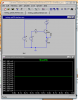
The second attachment shows another idea I had, but this one doesn't seem so safe. It seems like I might get more voltage than I want kicked back into the SPD-20 trigger inputs (I don't want to send 12V up there...they seem pretty hardy, but I don't want to push it). Again: bad idea? Good idea? Any way to make it a good idea, if it is in fact a bad one as shown? Maybe resistors between the SPD plug/lamp junctions?
Thanks for any input!
Torben
I have built a foosball scoreboard which works fine for me. It is based on TTL logic for the counting and LED display, and 555s for the trigger debouncing and win detection. The 555s trigger 3904s to light red 12V/20mA lamps when either player scores, and blue ones when either player wins. Now I want to add outputs which I can plug into the trigger inputs of my SPD-20 (Octapad-like unit with internal sound generators).
The circuit segment in the first attachment shows how I am currently switching the lamps in the bottom half of the image, and how I think I might trigger the SPD-20 in the top half. I tested the inputs on the SPD-20 and I like the sensitivity range it shows using 0.9V pulses, so that's what I set the voltage divider to for that section. (Actually, here's a side question: at the behest of someone I'm not sure I trust too much, there is also a 104 ceramic cap across each 3904's emitter and collector, and a 1n914 diode across each lamp--I think the diode is there because I mentioned the thought of powering small motors to ring bells instead of using the SPD-20. What are the caps doing there? Anything? It does work with them there...).
All lines coming from the BRAIN header are +5V pulses from the 555s.
I suspect the circuit will work (maybe even this weekend), but I wonder whether I couldn't save some parts and share the resistors between analogous 3904s. i.e. the SCORE1 lamp transistor and the SCORE1 SPD-20 trigger transistor would share a resistor, instead of having separate ones. Bad idea? Good idea?
The second attachment shows another idea I had, but this one doesn't seem so safe. It seems like I might get more voltage than I want kicked back into the SPD-20 trigger inputs (I don't want to send 12V up there...they seem pretty hardy, but I don't want to push it). Again: bad idea? Good idea? Any way to make it a good idea, if it is in fact a bad one as shown? Maybe resistors between the SPD plug/lamp junctions?
Thanks for any input!
Torben
")