Oznog
Active Member
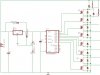
Your schematic shows an external diode in parallel with each PMOS.
This should not be necessary. All PMOS that you get off-the-shelf have an internal body diode inside in this direction already. You can read your spec sheet but usually they are capable of carrying substantial current.
Your schematic lacks a capacitor on the output of the reg. This could cause the reg to oscillate and potentially blow your chip.
You need to put a ceramic cap from Vdd to Vss right at the PIC chip, especially on a power circuit like this. I already had this trouble more than once- nearby power consumers, even though they didn't even draw power out of the reg, were causing the PIC to latch up.

")
