Continue to Site

Welcome to our site!

Electro Tech is an online community (with over 170,000 members) who enjoy talking about and building electronic circuits, projects and gadgets. To participate you need to register. Registration is free. Click here to register now.

  • Welcome to our site! Electro Tech is an online community (with over 170,000 members) who enjoy talking about and building electronic circuits, projects and gadgets. To participate you need to register. Registration is free. Click here to register now.

Roberts Unologic DAB/FM rechargeable radio power problems

Status
Not open for further replies.

andypandyplod

New Member
Hi,
I am trying to repair a Roberts Unologic radio,which when portable uses 4 X D cells,either alkaline or rechargeable which can be recharged by the roberts 7.5 volt 0.8 amp power supply which was supplied with the radio when new. The radio has stopped working correctly. I have checked battery connections and the power supply which were ok.When I measured at the 7.5v input I measured 56 ohms at all times,which to me would indicate a partial short. When the radio is connected to a 7.5v the display is overbright with all digits boxed out.When I supply the radio with a separate 6v supply it works fine including the lcd display.I assume regulation on the PCB has a problem.When I measure the current taken when working it shows about 350mA.This I believe is 200mA being used by the radio(normal) ,and 150 mA in the shorted component or components.
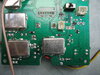
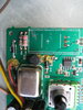
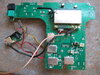
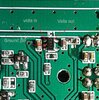
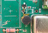
I cannot find any information of this fault,or circuit diagram (or schematic) on the Internet.The fault is not made easier by the PCB being double sided,and Roberts for some reason have put small tin screening cans over some components! I have never seen this on any other make of DAB radio. Any Help would be gratefully received please?
 
Photos would help.

Is the power supply a switch-mode one? Switchmode ones are light and small. Linear ones are heavy. What voltage does the power supply put out.

The metal screening cans would be quite common for a DAB radio. They may cover the power supply to stop it interfering with the receiver.

What current does the radio take when running on batteries, and does it work more normally?

The resistance measured at the input isn't a useful measurement, because the input won't follow Ohms law, and the current taken at the low voltage the the resistance meter produces won't relate at all well to the current taken at the normal voltage.
 
The resistance measured at the input isn't a useful measurement, because the input won't follow Ohms law, and the current taken at the low voltage the the resistance meter produces won't relate at all well to the current taken at the normal voltage.

Exactly - it's not something a service engineer would ever do, it's a completely useless 'test' - as it tells you nothing.

However, without a circuit, it makes life fairly tricky - and close to impossible to help remotely.

When I left the TV/Radio trade a few years ago it had already got to the stage that it was next to impossible to get Roberts service data any more.

Previously Roberts Radio official spares and service was done by a relatively small TV dealership - they were excellent, and extremely helpful - any problems and you could ring them and speak to someone who actually knew something. They could often advice solutions where spares were no longer available.

Then it changed to someone else, and went completely useless :D

I've just checked for the Unilogic, there are only SEVEN spares listed as available - and basically 'cosmetic' items - such as an aerial, knob, or rubber foot.
 
Thank you for replying.The Power supply came with the radio.It is a Roberts 7.5v 0.8A switched mode,and is supplying the correct voltage. The radio works fine on 4 Alkaline D cells,until the total voltage drops below 6 volts where the radio stops working,and the display is just blank yellow.If 4 NIMH cells are fitted,and the Alkaline/REchargeable switch is switched to rechargeable, the display is still blank,the batteriescharge about 300mA..This tells me the circuit which converts the 4.8 volts (4 NIMH cells) to 6 volts is not working. I have attached some photos.The battery charge ic is a SMD MC33340.I have removed the battery charging regulator 2SB1143 in these photos.THis reduces the current taken by the radio.
 

Attachments

  • IMG_0290.JPG
    IMG_0290.JPG
    3.2 MB · Views: 343
  • IMG_0292.JPG
    IMG_0292.JPG
    905.4 KB · Views: 267
  • IMG_0338.JPG
    IMG_0338.JPG
    2.8 MB · Views: 306
Help identify 5 pin smd device please?
Hi I may be getting nearer to finding where the fault might be. Underneath the display there is a 5 pin smd device which seems to be getting quite warm.Not sure if it is a voltage regulator to reduce 5v to 3.3v for the DAB receiver circuit?. I cannot find anything about the smd code of IC1 marked 'P0SJ'.The pinout of a Fairchild FPF2123 Load Management device is identical to the ground,Voltage in,and Voltage out tracks of IC1 on the PCB. I have attached a closeup of the PCB which shows the device I am trying to identify. I would be greatful if anybody can identify iC1 by its marking
 

Attachments

  • POSJ- 5 pin smd closeup a.jpg
    POSJ- 5 pin smd closeup a.jpg
    318.9 KB · Views: 405
The code POS J can possibly be a 3.3v regulator S-1200B33-M5T1x made by Ablic.
Page 24 of the datasheet, scroll down to product code POS & J is the lot code.
POS.jpg
 
Hi vtec,thank you for your good helpful reply.I was able to measure 3.3 v on pin 5(output pin) ,6 v on pin4 (Input pin); and pin 2 is connected to VSS,Ground,which is the same pinout as the device you suggested.The 3.3v output pin is connected to a pin on the DAB Module.I understand DAB modules need 1.2v and 3.3 v supplies.So it would appear this voltage regulator is working correctly. THe supply voltage to this device on my radio is 6 volts. I think it should be 5 v.I believe the fault may be in a 5v regulator circuit, but cant find one on the PCB,unless it is under a screening can.A good radio works on 4.8v (4 NIMH batteries).Why my radio works correctly on 6v I can't yet work out why. I have found a 3 pin device which seems to be shorted on all the 3 pins?.I measured this with the device still in circuit.It is marked 'XG'. I can only find devices which are a zener diode using this marking. I think it is a transistor? I have attached a photo showing the device which was completly covered in brown glue
 

Attachments

  • shorted 3 pin device.jpg
    shorted 3 pin device.jpg
    186.9 KB · Views: 253
you can try to search smd code on this website: www.marking-codes.com
on your picture,show POSJ smd code,try to search POSJ,but without any result,you can delete code "J",and search POS,you can get 4 result from this website.according to your info is a 5 pin smd part.so your item maybe is S-1200B33-M5T1x,check the datasheet,you can see the product code POS is for S-1200B33-M5T1x,and the code "J" is the lot number,so the item S-1200B33-M5T1x is the part for POSJ code
 
The device is working Ok ,it is giving the required 3.3v out. I believe the fault is on the Dab module,which is taking too much current,about 150mah more than I would expect..As the radio works fine when it has a 6v supply I am going to leave the radio as it is.I will not be able to charge 4 rechargeable batteries because it needs a 7.5 volt supply.
I dont agree with the early replies to my post. Checking the input with an ohmmeter is a good way to see if there is a short across the supply input.You are not looking for a specific reading just a reading which is lower than it should be.
Thank you very much for your input.
 
Status
Not open for further replies.

Latest threads

New Articles From Microcontroller Tips

Back
Top