Continue to Site

Welcome to our site!

Electro Tech is an online community (with over 170,000 members) who enjoy talking about and building electronic circuits, projects and gadgets. To participate you need to register. Registration is free. Click here to register now.

  • Welcome to our site! Electro Tech is an online community (with over 170,000 members) who enjoy talking about and building electronic circuits, projects and gadgets. To participate you need to register. Registration is free. Click here to register now.

RLC Circuit, Initial Conditions! - Noob Question

Status
Not open for further replies.
To the Ineffable All,

After t=0, my money says that a ammeter will indicate that current exists in a CCW direction.

Ratch
 
To the Ineffable All,

After t=0, my money says that a ammeter will indicate that current exists in a CCW direction.

Ratch

Hello,

Really? How much are you willing to put on that statement? :)
Yes, after t=0 that could be said to be true if you ignore the rest of the circuit, but while the cap is charging the ammeter will read positive, while it is discharging it will read negative, or if we connect it up with leads flipped it will first read negative and then later positive. Im sure this is easy to imagine.
I like the way Brownout put it though, in that the instructor is the ultimate customer.

In circuit analysis, we can say that positive current in the positive direction is the same as negative current in the negative direction, and that positive current in the negative direction is the same as negative current in the positive direction.
In the circuit given, originally the positive current is flowing in the CW direction. The current then either goes negative or changes direction.

We all know that the current really flows according to the electron flow, but we reverse that for convenience. What that means is physically the electrons can flow both ways, with some going CW and some going CCW. This averages out to one direction but still they are going in both directions.

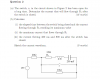
In the circuit, if we were not given the 20v source and the two 5 ohm resistors i would have analyzed it that way too. But if we want just one equation to describe the whole circuit for any time period we have to allow the current to change polarity.

If you still dont believe this, then solve this circuit for the underdamped case with C=0.005 F and see what the current does then before t=0 and also after t=0. It changes polarity, and that's not a big mystery. In oscillatory circuits it happens twice every cycle.

What do you want me to believe, that all of a sudden we are not allowed to let a current change polarity? What is the universe one big rectifier diode? he he.
God is up there on high looking at all circuits on the Earth and thinking, "Uh oh, there goes another current about to change polarity...i better swap the leads of the ammeter so no one knows it switched". :) Moses: "Thou shall not allow thy current to switch polarity" :)
I hope you guys appreciate the humor to lighten up the mood a little.
 
Last edited:
MrAl,

Yes, after t=0 that could be said to be true if you ignore the rest of the circuit, but while the cap is charging the ammeter will read positive, while it is discharging it will read negative, or if we connect it up with leads flipped it will first read negative and then later positive. Im sure this is easy to imagine.

I am only referring to current after the switch is closed at t=0. The ammeter will indicate current exists in a CCW direction according to conventional current. Ammeters are manufactured to be conventional current responding instruments.

Ratch
 
MrAl,


I am only referring to current after the switch is closed at t=0. The ammeter will indicate current exists in a CCW direction according to conventional current. Ammeters are manufactured to be conventional current responding instruments.

Ratch

Ok, but what does that prove? In circuit analysis we can choose any direction we want to, as long as we are consistent.
If you would like to say that after t=0 positive current flows CCW that's up to you, but then you'll have to say that before t=0 either that it flows CW or it is negative.
The only difference is what we call the reference current. I used positive current in the CW direction as the reference current because it would be more convenient when viewing the *entire* circuit for *any* time.
And you *must* also evaluate the circuit *before* t=0 as well as after t=0 in order to solve this circuit question. You cant solve it without considering both directions (or polarities) of current flow, so it makes sense to stick to one direction.
If you would like to switch directions that's fine too i guess, but you'd have to indicate it somehow or at the very least acknowledge that it changed direction or polarity.
If you look at a graph of inductor current vs time you'll see the current positive while the cap is charging and negative while the cap is discharging, if you choose to use conventional current flow. There's no way we can skip one of these because we have to evaluate what happens to the cap before t=0.

Think of what would happen if we were asked to indicate the current through the resistor before t=0 *and* after t=0. If we say that i=1 amp before t=0 we could also say that after t=0, i=1 amp, but it would be good to show that it changed direction or more conveniently changed polarity.

The key point here is that we must evaluate before as well as after t=0 to get the answer.
 
Last edited:
MrAl,

Ok, but what does that prove? In circuit analysis we can choose any direction we want to, as long as we are consistent.

I can assume any current direction for calculation, but if I get a negative result, then the current direction is the opposite of what I assumed. Unless the direction is specifically given to me, I always assume a CW direction in a loop. I calculated a negative value for the current in this problem, so the conventional current really goes in a CCW direction after t>0. I am sure an ammeter would confirm that.

Think of what would happen if we were asked to indicate the current through the resistor before t=0 *and* after t=0. If we say that i=1 amp before t=0 we could also say that after t=0, i=1 amp, but it would be good to show that it changed direction or more conveniently changed polarity.

It is uninteresting and not part of the problem to know what the current was before t=0. All I know is that the current was zero at t=0 and the voltage on the capacitor was 10 volts. Those two values define the two initial conditions needed to solve the problem.

Ratch
 
MrAl,


I can assume any current direction for calculation, but if I get a negative result, then the current direction is the opposite of what I assumed. Unless the direction is specifically given to me, I always assume a CW direction in a loop. I calculated a negative value for the current in this problem, so the conventional current really goes in a CCW direction after t>0. I am sure an ammeter would confirm that.
There is no question what the ammeter would read. An ammeter shows positive current connected one way, and negative current connected the other way.

It is uninteresting and not part of the problem to know what the current was before t=0. All I know is that the current was zero at t=0 and the voltage on the capacitor was 10 volts. Those two values define the two initial conditions needed to solve the problem.
Ratch
Absolutely not true at all. It is of prime importance that we know how the current flows *before* t=0. Without that knowledge we could not know how the capacitor charges and the only way we can calculate the current (in any direction) is to first know how much voltage builds across the capacitor.
When you say "all i know is" that knowledge came from a knowledge of how the current flows before t=0. You had to look at the circuit and acknowledge that current was first flowing in the inductor before it could build up voltage across the capacitor. You also have to acknowledge that that very current eventually fell to zero or you would not know what the initial current in the inductor was.
 
Last edited:
MrAl,

There is no question what the ammeter would read. An ammeter shows positive current connected one way, and negative current connected the other way.

Yes, certainly. But anyone competent with an ammeter can determine the conventional current direction. It is not necessary for anyone else other than the person making the determination to know how the meter was connected.

Absolutely not true at all. It is of prime importance that we know how the current flows *before* t=0. Without that knowledge we could not know how the capacitor charges and the only way we can calculate the current (in any direction) is to first know how much voltage builds across the capacitor.
When you say "all i know is" that knowledge came from a knowledge of how the current flows before t=0. You had to look at the circuit and acknowledge that current was first flowing in the inductor before it could build up voltage across the capacitor. You also have to acknowledge that that very current eventually fell to zero or you would not know what the initial current in the inductor was.

For this problem, I could care less what the current was before t=0. All I need to know is that 10 volts was applied to the capacitor via R and L for a long time. No current calculation was needed. Only the voltage across the capacitor was necessary, which was easily determined by inspection. True, current did exist while the cap was being energized, but that value is not important in discerning the final voltage.

Ratch
 
"No, your characteristic equation should be i(t) = Ae^-t + Be^-2t . (eq. 1)"

Yep, forgot to put the "^" symbol.

"The first condition is applied for eq. 1, 0 = A + B"

Yep, got that, thats when t=0, i=0.

I will now take a look at why we differentiate i..
 
Ok, after the first few posts all the talk was about the current directions and the convention. I am pretty sure that your all correct because like many of you pointed out it all depends on choosing a direction and sticking to it...

Now I think the circuit is pretty clear... I will try to explain what happens at t<0 and at t=0 and at t>0 and tell me where I am wrong.

at t<0

The capacitor has charged up to 10v because of the potential divider. The current is constant and di/dt = 0. Thus the inductor can be considered a short circuit (while the capacitor is open circuit). This means no current flows into the 3ohm resistor.

at t = 0+

The switch is now closed and We can ignore the source and the two 5ohm resistors. We have an RLC circuit where Vc=10v.

Now, using KVL we know that:

Vc = iR+Ldidt

Assuming that the current is flowing in a clockwise direction (going into the Capacitor, even though it should be going the other way as the Capacitor is discharging through the 3ohm resistor)

we get:

-Vc = iR+Ldi/dt

I is 0A because (and this is where I am not sure) The capacitor cannot discharge in 0 time and so there will be no current flowing into the inductor or the 3ohm resistor. Thus:

-10 = 0R+1*di/dt

-10 = di/dt

This gives us the second condition.

differentiating the current equation at the start we get:

di/dt = -Ae^-1(0)-2Be^-2(0) = -A-2B = -A+2A=A (noting that 0=A+B from the first condition).

-10 = A

10 = B

and thus:

i(t)= -10e^-t + 10e-2t

Is this all correct?
 
Hi again,

Fouad:
That is the very same result i got.
This is probably a good time for you to look at current direction too in order to discern which way the current flows and it's polarity during charge and discharge.
Oh yeah i almost forgot, the reason we differentiate is so that we can generate another equation that is not linearly related to the original equation. We have two unknowns so we need two equations, and differentiating gives us a convenient way to get that second equation. We can't simply multiply both sides by some constant because then the two would be linearly related to each other, so we take a derivative and then we are ready to solve for the two unknowns after we consider the initial conditions.

Ratch:
I am not saying that you are totally wrong about your viewpoint, im just saying that i believe that no matter how you do it you have to show the current polarity and the direction. These circuits usually start to get more involved and this is good preparation for things to come.
For example, see the attached diagram to see what happens when the switch is subject to PWM. The circuit is redrawn and the assumed current direction is shown along with the assumed capacitor polarity. With the switch open to start (same as the original problem) the current goes positive, then as the switch is closed the current goes negative and so does the derivative di/dt. As the circuit switch changes state repeatedly, the current switches positive and negative. If you change the direction of that current arrow drawn in the schematic, you change the polarity of all the waves that's all.
This could be a prelude to the buck circuit.
Note also that this may be analyzed one way in a circuits analysis class and another way in a physics class, so we end up having to provide what the instructor wants in the end anyway.
 

Attachments

  • Prob02-S1.gif
    Prob02-S1.gif
    18.4 KB · Views: 149
Last edited:
fouadalnoor,

Ok, after the first few posts all the talk was about the current directions and the convention. I am pretty sure that your all correct because like many of you pointed out it all depends on choosing a direction and sticking to it...

Yes, I always assume the current direction is CW direction unless the problem specifies otherwise. If I assume wrong, the current will be a negative value.

at t<0

The capacitor has charged up to 10v because of the potential divider. The current is constant and di/dt = 0. Thus the inductor can be considered a short circuit (while the capacitor is open circuit). This means no current flows into the 3ohm resistor.

Why are you interested in the current at t < 0? It will be a decreasing varying current through L and R while the capacitor is being energized. At t=0, the current will be zero.

Vc = iR+Ldidt

You forgot the term for the capacitor voltage. Why are you rehashing this again. You already solved for the complementary equation, i(t)= Ae^-t + Be-2t . Why drag differentials and integrations back into the solution? Did I not show you how to apply the two initial conditions to get the coefficients for the complementary solution?

Ratch
 
MrAL,

I am not saying that you are totally wrong about your viewpoint, im just saying that i believe that no matter how you do it you have to show the current polarity and the direction. These circuits usually start to get more involved and this is good preparation for things to come.
For example, see the attached diagram to see what happens when the switch is subject to PWM. The circuit is redrawn and the assumed current direction is shown along with the assumed capacitor polarity. With the switch open to start (same as the original problem) the current goes positive, then as the switch is closed the current goes negative and so does the derivative di/dt. As the circuit switch changes state repeatedly, the current switches positive and negative. If you change the direction of that current arrow drawn in the schematic, you change the polarity of all the waves that's all.

I said several times that I assume a CW current direction unless specified otherwise. The current values will change sign depending the the switch position, and the voltages will track those sign changes. You and I are doing the same thing, but presenting it in a different manner.

Ratch
 
Why are you interested in the current at t < 0? It will be a decreasing varying current through L and R while the capacitor is being energized. At t=0, the current will be zero.
Ratch

Because I want to find out if my understanding of what happens prior to the switch being closed is clear. From what I understand at t<0 the capacitor is fully charged up t=0+ and because it is fully charged it can be taken as an open circuit. Since there is a constant current going into the inductor then the inductor can be taken as short circuit?

You forgot the term for the capacitor voltage. Why are you rehashing this again. You already solved for the complementary equation, i(t)= Ae^-t + Be-2t . Why drag differentials and integrations back into the solution? Did I not show you how to apply the two initial conditions to get the coefficients for the complementary solution?
Ratch

Am I? I thought at t=0+ we could take the capacitor as a voltage source..and since Vc = 1/c integral i dt = 10v...

-10=3i+1*di/dt

since i = 0

-10 = di/dt

Also I am rehashing it again because I wanted to see if I understood everything right. By explaining the whole circuit myself you guys can tell me if im wrong. Also I brought the differentials and integrals back because I was not sure how you guys got di/dt = -10 and to me, what I did at the top proves that..
 
Last edited:
Hi again,

Take a look at the analysis plots i posted in my previous post. It shows the switch opening and closing, but it starts out open so you can look at the first cycle to get a better idea what is actually happening in this circuit while t<0 and at t=0 and for t>0. t=0 will be the point where the switch closes for the first time in the plots.

yeah, as expected the current flowing through the 3ohm resistor is 0amps before the switch is closed. It makes sense to me as the capacitor can be taken as open circuit while the inductor as short circuit. No current flows into a resistor with no potential difference across it.

When the switch is closed, the circuit behaves as specified by the function i(t) = -10e^-t+10e^-2t.

When t = infinity then i(t) = 0 (as shown)

when t = 1.5 (or around that point) i(t) = -1.7A (negative because its going anti-close wise)

yes?
 
Last edited:
......Yes :)
 
Last edited:
......Yes :)

Haha, that took quite a while for such a simple circuit! Finally I think I got it! Thanks a LOT I dont think I could pass my exams without you guys.

The notes that the lecturers give are just not that great, especially when none of them include any sort of numerical answer to compare with!

I am guessing that I should always try to find out how the circuit behaves in steady state to simplify things... if you look at this past exam question (attached) it's essentially the same as this question, just with a different arrangement.

Any other hints/tips you guys would suggest when attempting such questions?
 

Attachments

  • PastExamQuestion.png
    PastExamQuestion.png
    58.7 KB · Views: 152
Last edited:
Hello again,

The main ideas are to think about what the inductors and capacitors are doing after long periods of time. It's also a good idea to list the quantities as i pointed out in an earlier post as that helps identify what can be evaluated.

To help a little in your other studies, i am including a better generalized picture of a second order response to a step input. The one in your lecture notes is a bit misleading as it only shows the response for a damping factor of something like 0.1 or 0.2, while this new drawing shows representative waves for a bunch of damping factors. You can compare your results to these waves to get a better idea if you might be onto the right solution with that other circuit we talked about. Note that when zeta is 0.7 we get a much less oscillatory response then when zeta is say 0.1 or 0.2 . You also have to keep in mind that the amplitude of the response may be very much more or very much less than that shown in the generalized drawing. It could top out at only 1uv for example, or as high as 100000 volts just for example. That means if you graph the function you may have to 'zoom in' or 'zoom out' to see it properly.
 

Attachments

  • StepResponses-01.gif
    StepResponses-01.gif
    9 KB · Views: 153
  • ROOTS-01.gif
    ROOTS-01.gif
    31.1 KB · Views: 159
Last edited:
Status
Not open for further replies.

Latest threads

Back
Top