axro;799189]Well I'm more worried about the discharge aspect. I'm not really going to use this for a ripple counter, it was just the example I remembered. I was going to use a capacitor as the momentery switch needed for a monostable 555 timer.
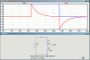
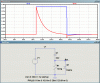
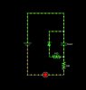
Here is my circuit, it's not the circuit i want, it's just a way of testing the discharge:

")