Continue to Site

Welcome to our site!

Electro Tech is an online community (with over 170,000 members) who enjoy talking about and building electronic circuits, projects and gadgets. To participate you need to register. Registration is free. Click here to register now.

  • Welcome to our site! Electro Tech is an online community (with over 170,000 members) who enjoy talking about and building electronic circuits, projects and gadgets. To participate you need to register. Registration is free. Click here to register now.

Rife and PEMF dual circuit help/question

Status
Not open for further replies.

drhiii

New Member
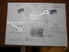
I have a very amateur level of competence when it comes to electronics, circuits, etc. Am looking at a Youtube project that combines a PEMF device (Pulsed Electromagnetic Field Therapy) and a RIFE device (Royal Rife, Tesla, etc).. dual circuitry. There are two or three elements in the hand drawn schematic that I do not understand and was hoping someone could put eyes on it and identify those pieces. I have sourced almost all of the parts, but a parts list would really have helped. I’ve tried to ask the originator of this schema but have yet to receive any replies. The engineer who drew this up posted barebones schema and vid, and I can almost get through it. Almost. So looking to this learned group for any help to interpret this schema and video.

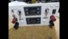
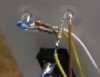
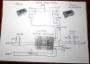
Am attaching an image with 2 balloons w/text and pointers asking “what is this?”, etc. Plus an additional question is… on the front panel there appear to be two, or three different kinds of lights. Are they all the same(for pulse, pulse, out, out and power), as in LEDs?, Or might they different kind of lights for the three different types/labels. Cannot discern from the schema and vid.

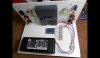
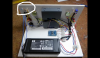
Am also attaching some images that snapshot the project, taken from the video.

Any advice would be most helpful. At the least

Fwiw, the end game of this is the PEMF aspect assist my wife who lives in chronic pain (6 total joint replacements for instance). Additionally, she is a liver transplant recipient.. so lots going on here. The magnetic pulse fields do provide a measure of relief. Hence why am pursuing this.


Youtube link:

Schematic: https://snag.gy/ZGwE8N.jpg
 

Attachments

  • Frex+PENF-internal.jpg
    Frex+PENF-internal.jpg
    71.5 KB · Views: 164
  • Frex+PEMF-FrontPanel.jpg
    Frex+PEMF-FrontPanel.jpg
    68.7 KB · Views: 134
  • Frex+PEMF-SchematicwithPots-withQuestions.jpg
    Frex+PEMF-SchematicwithPots-withQuestions.jpg
    315.3 KB · Views: 163
The rectangle on the left is another 1.5K resistor, like the one on the right. The stripe-y symbol is the industry standard symbol for Ground (GND).

Ground is the reference against which all other voltages in the circuit are measured. The HP power supply makes a 19 V output. That is +19 V with respect to its ground. If the timer module makes a 5 V output, that is 5 V with respect to its ground. For multiple components and circuits to work together, they all have to agree on a common "reference potential". In other words, all of the grounds have to be connected. Sometimes this can be tricky, but your system is pretty straightforward.

What does "INPUT" (lower left corner) connect to/from? Depending on what it is, P2 might be shown incorrectly.

This is not the world's best schematic, but there is nothing blatantly wrong electrically.

ak

Thank you SO much for this lesson. I presumed the left item was the same resistor as on the right, a 1.5K resistor.

On the 'ground' symbol, yes, that is what I surfaced as well. Tho here is an additional question... what is the 'ground' connected TO? Yes, a sophomoric question, but not having an electronics background, and YES, agree the schematic is not the world's best which is why I struggled to decipher it... If you could counsel me on what this 'ground' connects to, I would be most appreciative.

The "INPUT" is a connection to a frequency signal device. In this instance, it is connected to the audio output of a Windows machine, running a frequency program called 'Frex', out of Australia. Terrific frequency program.

Anyway, I am most appreciative that you have taken the time to respond, and educate. You are the only person out of a slew of pleas for help that has responded. Hence am in your debt. Yes, I am reaching out as I explore a lot of modalities to help my wife. Liver transplant (26 years), 6 total joint replacements, and she lives in chronic pain. I built a simple DIY PEMF device using a camera flash, and it does have a positive effect with reducing her pain. Tho am well aware that more is not necessarily better.

So am pursuing primarily the PEMF side of this device in a pursuit of a stronger device that may help more. Commercial devices, aka Doug Coils among other PEMF type device, can run in the many thousands. Hence why I am pursing a DIY effort.

Hope that you will respond. Your original response is much, much appreciated.
 
The box thing in your circle as mentioned is the resistor for the Led, it just flashes when theres a pulse on the output.

It took me a second but I think I know what the gnd legend connection is for, the signal generator has 2 supply terminals, one for power + and one for power -, and also has 2 terminlas for the output, one is the signal (marked Pwm on your sketch) and the other is signal ground, which is the ground symbol on your drawing.

I've seen Tens machines that use electrodes, but nothing like this, let us know if its successful.
 
Guy I used to work with has a spiral fracture in his leg that was not healing fast enough. Wore a PEMF rig for a few months, all better now. Belt pack with batteries and drivers, velcro pad with coil inside wrapped around the calf. Insurance covered 100%, an interesting statement of credibility.

ak
 
Hello, thought I would try and come back for a follow up question given that I received responses from here, to the prior plea for help on this circuit. Note that I was able to raise the engineer who crafted this original circuit and he gave an answer that I somewhat understand… but hoping someone could clarify the addition of two resistors that are NOT part of the original schematic.

I have attached a visual snapshot of the entire circuit with these additional resistors, a second snapshot zoomed in to point in question, and also the overall schematic that does NOT include these additional resistors and what I believe is a fuse that am looking for help on answering. So…..

Question is… on the LED that displays as the Power on/off indicator, I saw in the video (and extracted a snapshot) that there were two resistors and what I believe is a fuse. This was not in the original schematic. I asked what these were and his reply was “These are serial resistors that serve to reduce the current through the LED diode and have a value of about 1 Kohm. In addition, these LEDs only serve as a visual indication and have no impact on the work of the device.”

I understand the LED for power indicator is optional sure. I would like however to add this LED to the circuit. What I am looking for help on is… are these resistors simply a 1K ohm, ½ watt resistor? And by serial, how are they wired? Note that this is for a 19v power supply which is used in the original design. But this circuit can go up to 36v.

So for a 19v power source, what are these resistors, how would this be wired in a 19v power source? Serial as in 1K ohm + 1K ohm soldered to the pot? Or how would this be wired? I cannot quite make this out in the snapshot.

And secondly, what would be required if one were utilizing a 36v power source? A different resistor? How would that be wired?

And, I assume the blue object in the snapshot is a fuse??? Is one really needed and if yes, can someone also clue me in on its description so I can order it, and how is it wired within the mix of the 19v and 36v circuit?

Any advice will yet again be much appreciated. I can follow directions, am decent at soldering and constructing things… but am not trained in electrical engineering hence as the saying goes.. “a little knowledge is... etc etc etc.”

thank you for any advice on this...
 

Attachments

  • SerialResistors.png
    SerialResistors.png
    676.6 KB · Views: 143
  • PEMF-RIFE-PPowerSupplyLed.jpg
    PEMF-RIFE-PPowerSupplyLed.jpg
    15 KB · Views: 118
  • Frex+PEMF+Pots-original.jpg
    Frex+PEMF+Pots-original.jpg
    419.5 KB · Views: 237
LED resistors - he used two resistors in series because that is what he had, or that decreases the power dissipation in each one, or some other reason. If he used a single 2K 1/4 W resistor (looks like a 1/4 W body size to me), the power dissipation would be 144 mW. This is over 50% of the max power dissipation rating, a line that should not be crossed for good long term reliability. For a different power supply voltage, you need a different total resistance for the same current (hence, same brightness). A 36 V source would be 34 V across the resistor. For 8.5 mA LED current, you end up with 4.47K and 0.29 W.

The blue part almost certainly is another resistor from a different manufacturer. Yageo (Digi-Key favorite) uses a blue body for their 1% tolerance parts.

ak
 
One point of interest, the PWM signal generator (I have some bare PCB versions of it) outputs PWM pulses of the full supply rail, so in this case 19V odd p-p.

The only attenuation between the 19V and the input of the amplifier is the 10K pot, so it will only work at the very lowest volumes, above that the amplifier will be overloaded and the pot will make no more difference. I would suggest fitting a series resistor between the output of the module and the top of the pot (dropping the maximum level to less than 2V) giving a much greater useable range on the pot.
 
Disconnect the + wire to the Led, connect one end of a resistor to the Led +, then connect the other end of the resistor to the wire that went to the + of the Led.
Roughly you can multiply the Led voltage by 100, then choose the nearest resistor value, so 19v = 1900 ohms, or nearest 2200 ohms or 2k2 would work, and 36v 3600ohms or 3k9 would work, over 12v you'd need a 1/2 w resistor.
 
Having reaped some helpful advice to my queries, thought I would pop back in for another round.

On the aforementioned RIFE/PEMF device… I followed directions for a PEMF only device using the PWM signal generator and got it working. That was the aspect of all this I was most interested in. Was able to get it working on a 19v computer power supply source. No problem. I then attached a variable PS and pushed 30-36v into the circuit. A noticeable increase in power to the coil. Am also awaiting receipt of a 3k9 resistor recommended by Dr Pepper, to run that test.

But given the marked increase after running 30v 3a into the circuit, I was greatly encouraged by the power presented in the coil. Soooooo, not wanting a heavy arsed variable power supply connected to this circuit, I have been looking around for a small footprint 30v 3-4a power supply source to drive this. Everything I run in to has been either 30v and low amp, or none at all. And a standard 19v laptop power supply is significantly lower powered than what I experienced with this variable PS I placed on the circuit last eve.

So here’s my new pursuit which I hope someone could point me towards a solution. Am just looking for a small power supply, transformer, something… that can push 30v and 3+amps into this super simple circuit. Having searched around, was hoping I would come across a laptop PS that came close, but nawp. Anyone have an idea how I can accomplish this power supply need? 30V 3+ amps? Small footprint. so it all can fit in a shoebox sized enclosure. Would be much appreciated…

And if one can't tell, I have minimal electronic engineering skills. My soldering is getting much better tho. Anyway.. would one way to solve this possibly be to acquire a 36v (inexpensive) power source and step it down to 30v. Dunno how to manipulate amps tho. The need to keep above 3-4amps in the circuit was quite noticeable. Did I expose my lack of electrical engineering skillset? Am just trying to solve this PEMF device as it does help my wife and as mentioned, she lives in chronic pain... but being able to affect even a portion of that with this device is a big thing.
 
Last edited:
And on my prior post, also looking to keep costs lower than arm and partial leg. Once I solidify this functionality, am looking to make perhaps 4 - 5 of these, for family and couple of friends... to help reduce pain and inflammation which have found PEMF devices definitely do.
 
If you reduce your requirement to 24 V, there are a ton of low cost industrial supplies on ebay.

ak
 
Yes, I have been looking at this may be the way to go. But figured I would ask anyway... if anyone had an idea for 30v and 3+ amps, small PS.

But yessir, you may be right after all. I appreciate your response to this.


If you reduce your requirement to 24 V, there are a ton of low cost industrial supplies on ebay.

ak
 
Variable bench supplies are no longer super expensive, one of these maybe suitable for you.
 
If you reduce your requirement to 24 V, there are a ton of low cost industrial supplies on ebay.

ak

I have sourced as you indicated many 24V power supplies. Question, would 24V and 6A be appropriate for this circuit? Or better to lower the amps?
 
if you are plugging this into the wall, and connecting DIY circuitry to your wife, I would recommend a medical grade supply with short circuit protection, over voltage protection and decent insulation and cord strength & durability.

Here, 4amp, 30v - multiple connector sizes included.
, $55 plus shipping.
Edit - and you need the power cord to the wall...


Last edited:
Agree with Gophert, medical grade supply or batteries. How long is this device used in each session?

I hadn't heard of this so did a little digging. The main Rife stuff seems to suggest an RF frequency of 27MHz modulated at audible ranges. The above circuit is using an audio amp, what frequency does this operate?

Mike.
 
if you are plugging this into the wall, and connecting DIY circuitry to your wife, I would recommend a medical grade supply with short circuit protection, over voltage protection and decent insulation and cord strength & durability.

Here, 4amp, 30v - multiple connector sizes included.
, $55 plus shipping.
Edit - and you need the power cord to the wall...

Very good for the reference. I tried both links and both failed. If you can repost to a working link, that would be most excellent. Agree with your assessment also..


Agree with Gophert, medical grade supply or batteries. How long is this device used in each session?

I hadn't heard of this so did a little digging. The main Rife stuff seems to suggest an RF frequency of 27MHz modulated at audible ranges. The above circuit is using an audio amp, what frequency does this operate?

Mike.

Let me qualify this. The original post involved a RIFE/PEMF dual function circuit. In the last few posts, I reverted to a PEMF (pulsed electro magnetic field) that the person who posted the original youtube diy, also posted an earlier PEMF design only. That is what I am working to build at the moment.

So PEMF is more towards magnetic pulsing, tho frequency is, can be part of the delivery. RIFE is frequency based. This is way oversimplified explanation. Way more to these different protocols. Anyway...

Professional PEMF devices if one searches around are very expensive. And can utilize a powerful magnetic field. The PEMF device circuit I am working with now uses the same PWM signal generator as the dual RIFE/PEMF device posted at the beginning. As others have remarked, it is low powered. So realistic expectations are... how long is a therapeutic session? 20-60 minutes with a professional PEMF device. A low powered one as this… hour to hours.

As mentioned earlier, I had built one with a Minolta camera flash. Rudimentary for sure. But the dang thing works. Provides relief.. and this is on a person who lives in chronic pain. 6 total joint replacements, nerve damage, etc etc. So this is why I am pursuing this knowing it is a super simple circuit. But if I can construct something where one does not have to press a button to flash every 2 seconds, or drape magnet after magnet over pain sites.. even if the sessions take much longer, no problem. Am posting the link to the PEMF only design below. Waaaay way simple. The aspiration is to try and squeeze a bit more power from the original. In tweaking it from the original, incl using advice from here, have found have been able to advance the power through the coil I would say has increased at least 50%. Pretty good. Quite good in fact. So as said… to be able to squeeze a little more power out of this ultra simple circuit… that is the aspiration.

Relief from pain is not a small thing. Significant $$ can get spent on pain relief tools. We don’t have those kinds of $$. Side note is my wife is also a liver transplant recipient. We deal with a lot of different things. I know the length of this post is annoying for such a simple circuit. Especially coming from a novice. But having improved this initial design already, even an additional 15-20% power would be a big deal. I take in all advice, which is why of all the things I’ve pursued, not the least of which is the help here (more than I’ve received anywhere else I might add)… this super simple PEMF device is creeping up onto being a not insignificant tool. Matters.

Pardon the length.

 
I'm wondering if an Arduino with an H-bridge shield could be all the circuit you need. Plus a coil of course.

Do you have any links to discussions of pulse duration, frequency, intensity? Does it have to alternate - I.E. reverse polarity?

The fact the camera flash worked suggests that low frequency high intensity pulses work just as well.

Mike.
 
Status
Not open for further replies.

Latest threads

New Articles From Microcontroller Tips

Back
Top