Continue to Site

Welcome to our site!

Electro Tech is an online community (with over 170,000 members) who enjoy talking about and building electronic circuits, projects and gadgets. To participate you need to register. Registration is free. Click here to register now.

  • Welcome to our site! Electro Tech is an online community (with over 170,000 members) who enjoy talking about and building electronic circuits, projects and gadgets. To participate you need to register. Registration is free. Click here to register now.

RF Amplifier

Status
Not open for further replies.

hantto

Member
Hello!

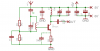
I've tried to design a high-frequncy antenna amplifier that only amplifies frequenzies around 392MHz. I've browsed through Harry's pages and various other sites and found information on basic transistor amplifier design and so on. And here I have the fruits of my efforts :p

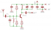
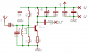
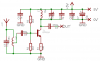
I must point out that this is my first self designed transistor amplifier. I have the schematic and some of my calculations attached. Will this amplifier work? I'm trying to receive an ASK-modulated signal (yes my rfPIC).

Thanks for your time, I'm looking forward to any responce I might get. :wink:

I'm a bit unsure about the currents in the circuit, is 10mA collector current too much for a preamp?
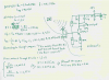
 

Attachments

  • amp.png
    amp.png
    299.6 KB · Views: 567
I think that the value of the input capacitor should be much less. Right now the preamp will be overloaded by every RF signal including 1MHz AM radio stations.
Maybe the input should have a parallel tuned circuit to ground so the transistor isn't overloaded by everything.
 
I don't see any problem with your circuit. The BSR92A is not a low level transistor, but it should work. It is in a sot-23 (surface mount) package, are you planning on making a PC board? You will need care in layout because the transistor Ft is 5 gHz and it will oscillate if you look crosseyed at it.
 
akg said:
audioguru said:
Right now the preamp will be overloaded by every RF signal including 1MHz AM radio stations.
pls explain.. since the collector is a tuned ckt , all other freq sees a short (say) ckt, then how can it be overloaded.?

Because the INPUT is accepting everything, you should have a tuned circuit on the input as well - being careful to avoid interaction between the two tuned circuits.
 
Wow! Thank you all for the the suggestions!

A tuned circuit at the input sounds like a good idea :). The only thing that has me worried is that will the antenna capacitance have an effect on the tuning of the input LC circuit? That was the original reason why I put the tuned circuit at the collector. Will the antenna coupling capacitor nullify the antenna capcitance?

I updated the circuit and made a preliminary PCB layout. Is it better now, did I add the input tuned circuit correctly? Any comments on the PCB? I didn't include the component names or values on the PCB because it would get too messy.

I added much decoupling in the hope that it will prevent the tuned circuits from interacting with eachother, as suggested earlier.

Russlk said:
The BSR92A is not a low level transistor, but it should work.

What did you mean by "low level transistor"?
 

Attachments

  • pcb.png
    pcb.png
    23.2 KB · Views: 467
  • schematic_482.png
    schematic_482.png
    16.1 KB · Views: 465
Woops! I must point out that I have an additional brain fart in my original calculations (Well, I guess that's what I get from staying up to 2am :lol: )

In the base current calculations I have written hfe = Ic/Ib --> Ib = Ic*hfe BUT it should naturally be Ib = Ic/hfe, but I had obviously calculated it right, just written the equation wrong. :lol:
 
hantto said:
Wow! Thank you all for the the suggestions!

A tuned circuit at the input sounds like a good idea :). The only thing that has me worried is that will the antenna capacitance have an effect on the tuning of the input LC circuit? That was the original reason why I put the tuned circuit at the collector. Will the antenna coupling capacitor nullify the antenna capcitance?

It's usual to connect the antenna to a tap on the coil, something about 1/4 from the bottom should be something like.

Basically the tuned circuit is a high impedance, and the antenna a low impedance, using the tap matches better, and gives gain via transformer action. However the transistor input is also low impedance and will 'flatten' the coils peak, and could be tapped as well.

As is often suggested, you could do with a copy of the ARRL or RSGB handbooks, these are INCREDIBLY useful, and not just for RF design - really EVERYONE on these forums should have a copy. Doesn't matter about a new one, old ones might be even better!.

To prevent feedback between the coils place them at 90 degrees to each other, and it's quite common to place a screen between them (often actually across the transistor).
 
Nigel Goodwin said:
It's usual to connect the antenna to a tap on the coil, something about 1/4 from the bottom should be something like.
Do you mean the coil on the base?
Only I'm using surface mount components, so tapping can be a bit of a problem. But hey! I could use two inductors in series with the values of aproximately 4:1. But the LC circuit would still be tuned with antenna and with the surroundings objects' capacitance's?

Nigel Goodwin said:
Basically the tuned circuit is a high impedance, and the antenna a low impedance, using the tap matches better, and gives gain via transformer action. However the transistor input is also low impedance and will 'flatten' the coils peak, and could be tapped as well.
I do not understand what you mean by "tapping the transistor"? Or did I completly miss your point here?

Nigel Goodwin said:
As is often suggested, you could do with a copy of the ARRL or RSGB handbooks, these are INCREDIBLY useful, and not just for RF design - really EVERYONE on these forums should have a copy. Doesn't matter about a new one, old ones might be even better!.
Yes I would, but from where can I obtain them? :\ I have not seen them in stores here in Finland.

Nigel Goodwin said:
To prevent feedback between the coils place them at 90 degrees to each other, and it's quite common to place a screen between them (often actually across the transistor).
Ok! :)

I would like to keep this circuit as simple as possible. My goal is to catch the the 392MHz signal from the air.
 
hantto said:
Nigel Goodwin said:
It's usual to connect the antenna to a tap on the coil, something about 1/4 from the bottom should be something like.
Do you mean the coil on the base?
Only I'm using surface mount components, so tapping can be a bit of a problem. But hey! I could use two inductors in series with the values of aproximately 4:1. But the LC circuit would still be tuned with antenna and with the surroundings objects' capacitance's?

Using two coils isn't the same 8)

At the frequency in use, presumably you're using an air cored coil, it's usually easy to solder a tap part way up the windings - generally you would wind the coils yourself, it's not hard to wind a few turns.

Nigel Goodwin said:
Basically the tuned circuit is a high impedance, and the antenna a low impedance, using the tap matches better, and gives gain via transformer action. However the transistor input is also low impedance and will 'flatten' the coils peak, and could be tapped as well.
I do not understand what you mean by "tapping the transistor"? Or did I completly miss your point here?

Sorry if I wasn't clear, I meant connect the base to a tap on the coil!.

Nigel Goodwin said:
As is often suggested, you could do with a copy of the ARRL or RSGB handbooks, these are INCREDIBLY useful, and not just for RF design - really EVERYONE on these forums should have a copy. Doesn't matter about a new one, old ones might be even better!.
Yes I would, but from where can I obtain them? :\ I have not seen them in stores here in Finland.

How about Amazon.com?.

Nigel Goodwin said:
To prevent feedback between the coils place them at 90 degrees to each other, and it's quite common to place a screen between them (often actually across the transistor).
Ok! :)

I would like to keep this circuit as simple as possible. My goal is to catch the the 392MHz signal from the air.
 
Nigel Goodwin said:
Because the INPUT is accepting everything, you should have a tuned circuit on the input as well - being careful to avoid interaction between the two tuned circuits.
yes that i understand , but the instaneous collector voltage depends on Rc, if that is zero (or very small) , then..will it get overloaded ?
 
Nigel Goodwin said:
hantto said:
Nigel Goodwin said:
It's usual to connect the antenna to a tap on the coil, something about 1/4 from the bottom should be something like.
Do you mean the coil on the base?
Only I'm using surface mount components, so tapping can be a bit of a problem. But hey! I could use two inductors in series with the values of aproximately 4:1. But the LC circuit would still be tuned with antenna and with the surroundings objects' capacitance's?
Using two coils isn't the same 8)

At the frequency in use, presumably you're using an air cored coil, it's usually easy to solder a tap part way up the windings - generally you would wind the coils yourself, it's not hard to wind a few turns.

Ok, I'll handwind a coil for the base.

Nigel Goodwin said:
Nigel Goodwin said:
Basically the tuned circuit is a high impedance, and the antenna a low impedance, using the tap matches better, and gives gain via transformer action. However the transistor input is also low impedance and will 'flatten' the coils peak, and could be tapped as well.
I do not understand what you mean by "tapping the transistor"? Or did I completly miss your point here?
Sorry if I wasn't clear, I meant connect the base to a tap on the coil!.

Now, if I connect the base to a tap like in the schematic below, wouldn't it upset the transistors bias? Come to think of it, doesn't the whole tuned circuit at the input pull the base to 0v? rendering the amp inoperable?


Nigel Goodwin said:
Nigel Goodwin said:
As is often suggested, you could do with a copy of the ARRL or RSGB handbooks, these are INCREDIBLY useful, and not just for RF design - really EVERYONE on these forums should have a copy. Doesn't matter about a new one, old ones might be even better!.
Yes I would, but from where can I obtain them? :\ I have not seen them in stores here in Finland.
How about Amazon.com?.

I don't like the idea of ordering stuff from strange and mysterious countries :lol: Especially when you have to fiddle around with the currencies. I think I'll skip that and go to the local library and see what I can find.
 

Attachments

  • schematic2.png
    schematic2.png
    21.6 KB · Views: 456
hantto said:
Now, if I connect the base to a tap like in the schematic below, wouldn't it upset the transistors bias? Come to think of it, doesn't the whole tuned circuit at the input pull the base to 0v? rendering the amp inoperable?

Yes, but that wasn't what I meant, I presumed you would know what to do?, connect the coupling capacitor from the tap to the base, obviously leaving the bias components connected to the base.
 
Nigel Goodwin said:
hantto said:
Now, if I connect the base to a tap like in the schematic below, wouldn't it upset the transistors bias? Come to think of it, doesn't the whole tuned circuit at the input pull the base to 0v? rendering the amp inoperable?

Yes, but that wasn't what I meant, I presumed you would know what to do?, connect the coupling capacitor from the tap to the base, obviously leaving the bias components connected to the base.

Oh :lol:

Is this better?

You got me quite confused with what should tap to what. Should the antenna be tapped to the coil, or the transistor base be tapped to the coil? I got the impression that both should be tapped, ie. connected to the same point? That wouldn't have any possitive effect on the circuit.
 

Attachments

  • schematic3.png
    schematic3.png
    21.2 KB · Views: 493
AKG,
When the input of a transistor RF amplifier is overloaded by having many strong signals then the transistor's output is full of intermodulation of those signals and the desired signal is not amplified.
 
Hantto

I dont know if this helps but here is a photo and circuit diagram of an amplifier which I built some years ago,

It is intended for 432Mhz, and has a gain of about 20dB.
It is built out of what was in the junk box, using "ugly" construction. It is not pretty, but it is stable.

The coils are short lengths (about 25mm) of 1mm diameter coper wire. The variable capacitors are about 10 pF.

JimB
 

Attachments

  • circuit_910.jpg
    circuit_910.jpg
    28.8 KB · Views: 446
  • amplifier_209.jpg
    amplifier_209.jpg
    95.1 KB · Views: 432
Nice one Jim!, that's the sort of thing - although I was trying not to confuse things further by suggesting lecher lines 8)

Notice that using an FET allows a direct connection to the top of the input tuned circuit, and also that the output tuned circuit is tapped as well.

Nothing wrong with 'ugly' construction, as I'm sure you're aware, it's a VERY suitable format for high frequencies - and I suppose is a simple form of surface mount?
 
You can eliminate the loading effect of the bias network by moving it. See below. You can also pick up more gain by bypassing the emitter resistor.
 

Attachments

  • schematic4.png
    schematic4.png
    24.2 KB · Views: 402
Ron H said:
You can eliminate the loading effect of the bias network by moving it. See below. You can also pick up more gain by bypassing the emitter resistor.

Thanks Ron H!

I think I'll build that circuit and see how it works. I'm not going to confuse myself further with fets or leecher lines. But thanks for that schematic Jim, I hadn't seen a circuit with leecher lines before. I already have BFR92As so I'm going to use them.
 
Status
Not open for further replies.

Latest threads

New Articles From Microcontroller Tips

Back
Top