Continue to Site

Welcome to our site!

Electro Tech is an online community (with over 170,000 members) who enjoy talking about and building electronic circuits, projects and gadgets. To participate you need to register. Registration is free. Click here to register now.

  • Welcome to our site! Electro Tech is an online community (with over 170,000 members) who enjoy talking about and building electronic circuits, projects and gadgets. To participate you need to register. Registration is free. Click here to register now.

Reverse Polarity Pulse Circuit Help!

Status
Not open for further replies.

green_orko

New Member
Hi All,
First post so please be gentle ;)

I am trying to set up an automatic watering system. This is filled up via a solenoid valve connectde to the mains. However the solenoid valve requires a 30ms - 60ms pulse to activate the coil and then another 30ms - 60ms reverse polarity pulse to deactivate.

I have been attempting this for a few weeks now but to be honest I really am struggling.

Can anyone please please help me with a simple diagram - I am not even close!

Thank you !!
Rich
 
BYTW - this is based on a 5v DC supply and a 9v DC solenoid valve.

ta

There is your problem, right there :confused: You need 9V to power a 9V solenoid :p

Do a quick search for H-Bridge. One made out of two relays will work. What determines when to close and when to open the valve?
 
Hi Mike,
I was a bit unclear.. I have two float switches that operate a 5v relay. When the water level drops this relay then has to switch the 9v DC solenoid valve via a pulse. The level reaches a top float switch and then operates the solenoid valve via a reverse pulse...

Thanks
 
How much current does the pulse have to supply (or what is the DC resistance of the solenoid coil)?
 
Sounds like a job for a 555 timer monostable, connect the input to your float switch and the output to a transistor (or other device of your choosing) to drive the solenoid. Can't remember if there is a simple way to make the 555 produce + or - pulses but it should be easy to find out or work out.
 
Hi Mike,
I was a bit unclear.. I have two float switches that operate a 5v relay. When the water level drops this relay then has to switch the 9v DC solenoid valve via a pulse. The level reaches a top float switch and then operates the solenoid valve via a reverse pulse...

Thanks

I have worked out a solution using relays.

Can you get a 12Vdc 1A supply? (This is used to pulse the valve).
Does the Full Float switch have SPDT (NO-C-NC) set of contacts? I need a normally closed set of contacts that open when the tank is full.
 
Look at this. I dont have time to write a description tonight. Going to bed.
 

Attachments

  • Tank.jpg
    Tank.jpg
    370.7 KB · Views: 246
Finally have some time to get back to this:

Relay U1 is wired to latch on its own contact. When the level in the tank is between full and empty, the NC Full float switch is closed. As the tank drains, eventually, the NO Empty float switch closes, causing U1 to pull-in. As soon as it does, U1's own contact closes, meaning that it doesn't matter what state the Empty float is in. Assuming the valve is operated, the tank begins filling. When the level rises to where it opens the Full Float switch, that depowers U1, and it shuts off.

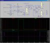
This is depicted in the simulation by the red and green traces. The Empty float switch is closed while the Red trace (a simulation control signal) is >0V. The Full Float switch is open while the Green trace is >0V.

The Blue trace in the lower plot pane shows the state of the Latch relay U1. Note that it turns on when the Empty switch first closes, and turns off when the Full switch first opens. The second set of contacts on U1 Create a signal that is actively driven to +12V, or to ground.

If you were using a normal solenoid valve, this is all you would need, because the Latch relay could control it directly.

The low-to-high edge of the Latch signal is used to pulse relay U2. Note use of steering diode D1 to create a pulse. The value of C1 and U2's coil resistance controls the time duration of the pulse. D2 steers the high-to-low edge of Latch to relay U3.

The contacts of U2 and U3 create an H-bridge which can drive current through the valve coil L1 in either direction. The current through L1 is shown in the Purple trace. Diodes D4 and D5 are snubber diodes which protect the contacts in U2 and U3.

I would use a single 12V supply to do everything. A 12V short duration pulse wont hurt your valve. I would look for 12V relays that have as high a coil resistance as possible. The cheap 12V Bosch automotive relays typically have a coil resistance of 85Ω, which will require a huge capacitor. I have some relays around here where the coil has polarity marks. These are internally biased with a permanent magnet, and have a coil resistance of ~500Ω. Those are the ones I modelled in the sim.
 
Hello Mike,
That sounds exactly what the doctor ordered! I'm sure even a man of my calibre can follow those detailed instructions. I will give it a whirl this weekend and hopefully be up and running!

I can't thank you enough! Have a great easter break and I will of course let you know how I go on!

I do have one more question... What software do you model your diagrams and actions with pls?
 
He's using LTSpice. You can download it for free from linear.com
 
Status
Not open for further replies.

Latest threads

New Articles From Microcontroller Tips

Back
Top