Continue to Site

Welcome to our site!

Electro Tech is an online community (with over 170,000 members) who enjoy talking about and building electronic circuits, projects and gadgets. To participate you need to register. Registration is free. Click here to register now.

  • Welcome to our site! Electro Tech is an online community (with over 170,000 members) who enjoy talking about and building electronic circuits, projects and gadgets. To participate you need to register. Registration is free. Click here to register now.

reverse polarity protection

Status
Not open for further replies.

Urahara

Member
Hi

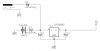
I have placed a diode in series to the + of a DC jack to provide reverse polarity protection for my circuit.

To test if it works, I set a wall wart to the reverse polarity. My circuit did not fry and can work using a 2nd wall wart set at the right polarity.

Why a 2nd wall wart? Because it seems that my first my wall wart is now not working!! (it was working earlier before this test).

Is this normal? Why? :confused:

Thks!
 
Did you change the first wallwart back to right polarity. Series diode has voltage drop and make sure that it won't affect the normal working of your circuit!
 
Yup. I set it back to the right polarity after the test and it stopped working. Thot the circuit was damaged. Used a second wall wart and it works. So circuit is ok, and the first wall wart is not.
 
Post a schematic. Show exactly what you did.
 
Was the protection diode in series with or in parallel with the circuit your are protecting?
 
Oh, put it at the ground side. This makes sure that no potential is seen on any components. Was the circuit hooked up to anything when you reversed it?
 
Unless I'm missing something, you could eliminate quite a few components in your circuit:
wallwart-png.30210


Don't know why your wall wart failed. It shouldn't have.
 

Attachments

  • wallwart.PNG
    wallwart.PNG
    16.1 KB · Views: 2,346
Was the circuit hooked up to anything when you reversed it?
The schematic posted was the power supply to power a PIC circuit.

Does the dead wall wart have an internal glass fuse? That's common.
Not sure. Everything's encapsulated. But how does this cause the fuse to blow?

Unless I'm missing something, you could eliminate quite a few components in your circuit:
Hi KChristie, my thought process is as follows, would appreciate your comments : one of my design considerations is to maximize batteries usage. using the schottky diodes to steer first would cause the batteries voltage to drop by 0.3v even before feeding it into the LDO regulator. Hence the steering is done after. The cons of my approach are additional components on the wall-wart end. But I get to maximize the usage of the batteries. True?

Btw, I tried the same experiment with my second wall wart, and it seems that my second wall wart is pretty much toast!! :(
 
Btw, I tried the same experiment with my second wall wart, and it seems that my second wall wart is pretty much toast!! :(


Well then you have a construction or wiring error that is short circuiting the wall wart module. As your drawing seems to have no fundamental errors and you have burned out two wall warts that leaves construction/wiring errors the most logical problem.

Lefty
 
Heres a circuit that will give the correct polarity on the output regardless of the polarity on the input....there is a slight voltage drop through the circuit but not much-try not to be too scared of it!!!
 

Attachments

  • POLARITY PROTECTION.pdf
    4.1 KB · Views: 531
using the schottky diodes to steer first would cause the batteries voltage to drop by 0.3v even before feeding it into the LDO regulator. Hence the steering is done after. The cons of my approach are additional components on the wall-wart end. But I get to maximize the usage of the batteries. True?
There will be little difference because you are still losing 0.3V in the diode whether it is before the regulator or after it. By putting the diodes after the regulators, you are degrading the regulation of the 7805 and LP2950 a bit. Also, by putting the diodes after the regulators, there is a big possibility that you will draw current from both the battery and wallwart when plugged in because they both put out 5V. By putting the diodes on the input, you would use a wallwart with a slightly higher voltage than the battery, eliminating that issue.
Btw, I tried the same experiment with my second wall wart, and it seems that my second wall wart is pretty much toast!! :(
Do these wall warts have a third AC prong? If so, this ground prong is possibly connected to the negative lead which would be a problem if your powered project is grounded through something else as well.
Most simple wallwarts (Non regulated & non -switching type) can tolerate a shorted output for quite a long time (many minutes) without damage.
 
Last edited:
There will be little difference because you are still losing 0.3V in the diode whether it is before the regulator or after it. By putting the diodes after the regulators, you are degrading the regulation of the 7805 and LP2950 a bit. Also, by putting the diodes after the regulators, there is a big possibility that you will draw current from both the battery and wallwart when plugged in because they both put out 5V.
Was trying to ensure that there is a min 0.5V difference between Vout and Vin as per datasheet, hence i placed the diode after the LDO. I am aware of the 0.3V drop after the LDO, but at least I know it would be 4.7V (5V - 0.3V). But redid my calculations and realise that both designs may not yield significantly different results. Your design may work out better since it is more compact, saves me some $$, and reduces unnecessary quiescent current at the LDO.

Will test that out and see if it is good. Thks!

Do these wall warts have a third AC prong? If so, this ground prong is possibly connected to the negative lead which would be a problem if your powered project is grounded through something else as well.
Most simple wallwarts (Non regulated & non -switching type) can tolerate a shorted output for quite a long time (many minutes) without damage
nope, mine's a two prong. from the various responses gathered, at least I know the wall wart is not suppose to fail.


Thks!
 
Status
Not open for further replies.

Latest threads

New Articles From Microcontroller Tips

Back
Top