Continue to Site

Welcome to our site!

Electro Tech is an online community (with over 170,000 members) who enjoy talking about and building electronic circuits, projects and gadgets. To participate you need to register. Registration is free. Click here to register now.

  • Welcome to our site! Electro Tech is an online community (with over 170,000 members) who enjoy talking about and building electronic circuits, projects and gadgets. To participate you need to register. Registration is free. Click here to register now.

reverse engineering the keypad module

Status
Not open for further replies.
Oh wow. There is a so much easier way to do this that only needs a single input to read all the switch presses. One digital input and nothing else, and simple code. I'll sketch it up later. Sooner with an appropriate bribe ;)
 
Givens:
12 LEDs
12 push button switches
Only one LED will be on at a time.
When the corresponding switch is pressed, there will be an output.

All port pins start as inputs.

To illuminate an LED, the column port pin is set to a high output. The row port pin is set to a low output.

The Switch Output line will be pulled high. When the associated switch is pressed, the Switch Output line will be pulled low.

Reset all pins to inputs and repeat.

Note: the switch output line will only be high when an LED is illuminated, and will be low while the associated switch is pressed.
 

Attachments

  • 20200309_144102.png
    20200309_144102.png
    29.7 KB · Views: 197
in post #34 is basically what you described.
I like your schematic but the sequence isn't correct?
Will ponder but still liking the ADC solution but worried about monitoring two ADC inputs or how many resistors can one use in a resistor ladder?
Will clean up my keypad12 schematic and post. Been hacking at it trying to figure out what is not working right. I found that it displays a key press on power up. Always coming up with #11 as per post 37.
 
The circuit I posted above is the simplest, straight forward approach. I don't know what the heck you mean that the sequence is incorrect.

This circuit does not use the keypad module.

Use it if you like. If not, have fun, you're on your own.
 
sequence needed= led1 comes on
player presses switch1 to turn off led1
led5 comes on
player presses switch5 to turn off led5
If I understand your schematic, pressing d4 turns on led4 etc.
No comments on using the ADC approach which uses fewer pins?
 
Can't you follow through a schematic?

Let's say you want to turn on LED1:

1. Make column 1 port pin an output and set it high.

2. Make row 1 an output, and set it low.

3. LED1 is illuminated.

4. The top terminals of S1 – S4 are pulled high via the 10k resistor connected to the column 1 port pin. This pulls the Switch Pressed Line high.

5. The bottom terminals of S1, S5 and S9 are pulled low via the Row 1 port pin.

6. Pressing S1 pulls the Switch Pressed line low. Pressing S2, S3 or S4 has no effect because their bottom terminals are floating, i.e., not connected to ground.

Awww crap. Pressing S5 or S9 will also pull the Switch Pressed line low. Slight change needed. You'll need a separate Switch Pressed line for each column. Still easier that what you are trying to do.
 
Slight modification. Total of 10 port pins to control 3×4 LED matrix and reliably detect the associated key press.
 

Attachments

  • 20200310_084823.png
    20200310_084823.png
    67.4 KB · Views: 200
No comments on using the ADC approach which uses fewer pins?

Yes. My comment was and remains, now that I understand you application, is that the way I have proposed (with slight modifications) is the best way to do it. The code is straight forward, and there's no confusion about which pin is pressed.

The long and short of it is I'm not going to try and untangle your logic and your code using either the keypad modules (since you refuse to use them "as is" or the ADC arrangement as it's more complex and subject to drift problems.
 
I have tried using the keypad module using several different test boards with no success.
going to reevaluate what I have and why it doesn't work. The keypad module I had working before.
just getting ticked off at myself.
Haven't given-up on your schematic either
 
going to reevaluate what I have and why it doesn't work
That would likely be because you've switched around the row(inputs) and column(outputs) pins from what the keypad module in post #37 is expecting,
and you don't know how to modify it to match your pin connections.

Can you post the original "keypad12.bas" module you started with?
It's not a standard library so I don't have a copy.
 
here is an orginal keypad12.bas
Code:
Module Keypad12
{
Column1 = PORTX.0
Column2 = PORTX.1
Column3 = PORTX.2
PORTX.3 NC
Row1 = PORTX.4
Row2 = PORTX.5
Row3 = PORTX.6
Row4 = PORTX.7
}

// validate data port...
#option KEYPAD_PORT = PORTB
#if IsOption(KEYPAD_PORT)
   #if Not IsValidPort(KEYPAD_PORT)
      #error KEYPAD_PORT, "Invalid option. Keypad must be connected to a valid port name."
   #endif
   #option _KEYPAD_PORT_TRIS = GetTRIS(KEYPAD_PORT)   
#endif

// bring PORT and TRIS options into the module
Dim
   FKeyPort As KEYPAD_PORT,
   FKeyPortTris As _KEYPAD_PORT_TRIS


Public Function Value() As Byte
    Dim Counter As Byte
    Dim RowData As Byte
    Dim ColData As Byte
    
    Result = 0                           
    Counter = 0
    For Counter = 0 To 2                //
        FKeyPortTris = $FF              // Make all pins inputs
        FKeyPortTris.Bits(Counter) = 0  // Make a single Column an output
        FKeyPort.Bits(Counter) = 1      //  and set it high
        
        If (FKeyPort >> 4) <> 0 Then    // Check if any Rows are "High"
            Coldata = Counter
            If FKeyPort.4 = 1 Then
                RowData = 1
            ElseIf FKeyPort.5 = 1 Then
                RowData = 4
            ElseIf FKeyPort.6 = 1 Then
                RowData = 7
            ElseIf FKeyPort.7 = 1 Then
                RowData = 10               
            EndIf           
            Result = Coldata + RowData
            Break         
        EndIf 
    Next
End Function

Public Sub Debounce()

    While Keypad12.Value <> 0           // Check if key is pressed
        DelayMS(10)                     // Wait for 10mS
    Wend 

End Sub

FKeyPortTris = $FF              // Make all pins inputs

End
 
Do you have a schematic for your current connections?
Are the keypad pullups connected to the rows or columns?
 
pullups are connected to the 4 colums
will draw up a readable drawing.
here is a snippet of code I wrote that actually works BUT sw_row3 acts like sw_row1
Code:
For x= 0 To 4
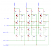
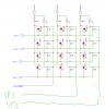
If SW_COL1=0 And sw_ROW1=0 //sw_colx =high via pullups until button press then it goes low
    
    Then
    key=1
delayms(30)
    sw_col1=1//
    sw_row2=1 sw_row3=1
ElseIf
    SW_COL2=0 And sw_ROW1=0  //searching for LOW
    Then
    key=2
    delayms(30)
    sw_row2=1 sw_row3=1
    sw_col1=1
    'sw_col2=1 sw_row1=1 sw_row3=1   //reset sw+colx
    
    ElseIf
        SW_COL3=0 And sw_ROW1=0
        Then
        key=3
  '      delayms(30)
        'sw_col3=1 'sw_row1=1
        sw_row2=1 sw_row3=1
        'sw_col3=1 sw_row1=1 sw_row3=1
            ElseIf
             SW_COL4=0 And sw_ROW1=0
             Then
             key=4
   '          delayms(30)
                sw_row2=1 sw_row3=1
                'sw_row2=1 sw_row3=1
            
        Break
        EndIf
    Next
     ' If key<>0 Then
    'DelayMS(50)
    WriteAt(2,1,"Key: ",DecToStr(key,2))//,( " Cnt: "),DecToStr(Counter,2)
    wend
 
the posted schematic is my actual pcb
yes I have verified all my connections


But you haven't actually shown WHAT the connections are. For example, what does Row 1 connect to? And the 10k resistors? What is Col 1? I think these are pullup resistors connected to +5V, but I don't have a clue where YOU have them connected. A schematic isn't a guessing game.

Furthermore, you don't show the LEDs or micro, so it's small bit of a schematic. Who knows what interferes there may be.
 
Status
Not open for further replies.

Latest threads

New Articles From Microcontroller Tips

Back
Top